Power supply extension cord

A technology of extension cords and power supplies, which is applied in the direction of circuits, electrical components, and devices with bendable leads. It can solve the problems of overall shape, single function, inability to realize hidden storage and arrangement, and inability to organize in bundles, etc., to achieve appearance design Novel, reliable and detachable connection, the effect of ingenious overall structure design

Active Publication Date: 2020-06-12
NINGBO YLK ELECTRICAL
View PDF6 Cites 0 Cited by
  • Summary
  • Abstract
  • Description
  • Claims
  • Application Information

AI Technical Summary

Problems solved by technology

Among them, the socket is generally designed as a long rectangle and has multiple electrical jacks along the length direction. The overall shape and function are relatively single.
[0003] And most cables are generally in a loose state when they are not in use. Even if they are organized, they need to be bundled with a separate binding wire. When the binding wire is lost or cannot be found, it cannot be bundled.
In addition, even if the bundled cables are used to organize, the bundled cables are exposed separately from the socket, and hidden storage and organization cannot be realized

Method used


Image

  • Power supply extension cord
  • Power supply extension cord
  • Power supply extension cord

Examples


Embodiment 1

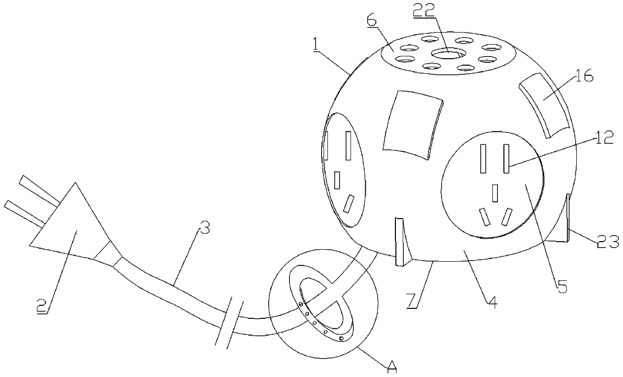
[0032] Attached below Figure 1-3 , 5, 6 as examples to describe in detail a power extension cord in the embodiment shown in the drawings. The power extension cord includes a socket 1, a plug 2 and a cable 3 connecting the two.

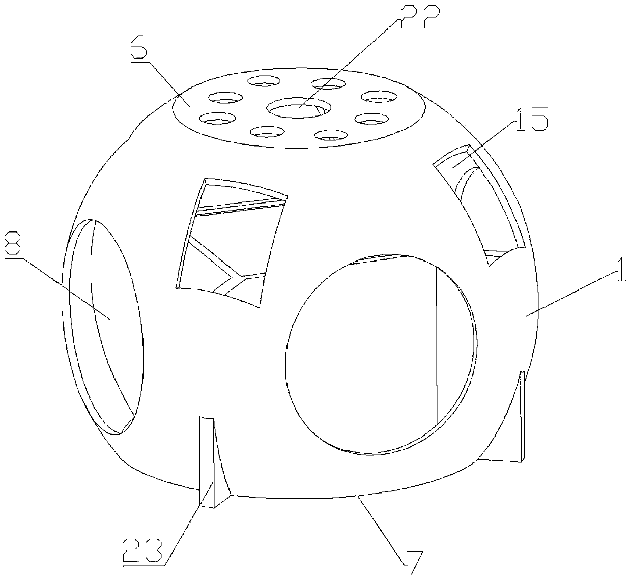
[0033] Different from the prior art, the socket 1 includes a spherical shell 4 and an integrated built-in body 5 . The spherical shell 4 is provided with a straight top sealing end 6 and a flat bottom opening end 7, and the spherical side walls between the straight top sealing end 6 and the flat bottom opening end 7 are provided with a plurality of uniform circumferential intervals. Cloth work wall holes 8.

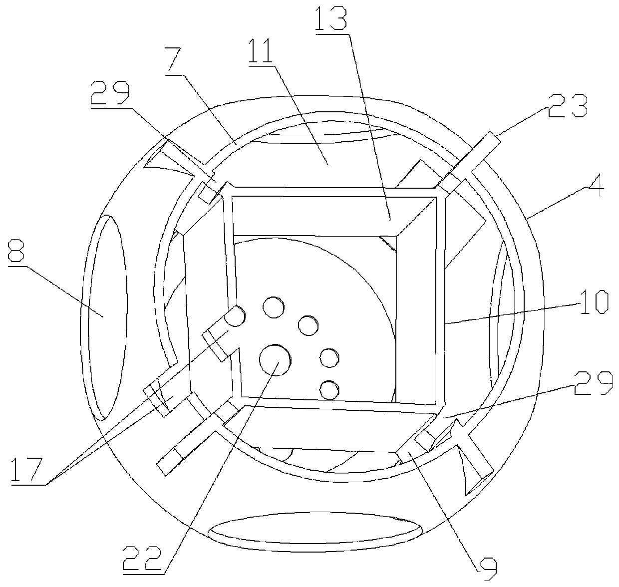
[0034] Fitting wall plates 9 extend radially on the inner wall of the ball between adjacent working wall holes 8 , and two adjacent fitting wall plates 9 are connected by a connecting wall plate 10 to form a configuration chamber 11 . It can be understood that the configuration chamber 11 is shared by two adjacent fitting wall panels 9 , the c...

Embodiment 2

[0041] Reference attached Figure 1-6 , this embodiment introduces a power extension cord in detail, the power extension cord includes such as Figure 1-3 Receptacle 1, plug 2 and cable 3 connecting the two are shown. Different from the prior art, the socket 1 includes a spherical shell 4 and an integrated built-in body 5 .

[0042] The spherical shell 4 is provided with a straight top sealing end 6 and a flat bottom opening 7 , wherein the flat bottom opening 7 is closer to the middle of the spherical shell 4 than the straight top sealing end 6 .

[0043] The ball side wall between the straight top sealing end 6 and the straight bottom opening end 7 is provided with a plurality of working wall holes 8 evenly distributed in the circumferential direction, and the upper edge of the inner wall of the ball between adjacent working wall holes 8 A fitting wall plate 9 extends radially. Two adjacent fitting wall panels 9 are connected via a connecting wall panel 10 to form a confi...


PUM


Abstract

A power supply extension cord comprises a socket, a plug, and a cable used for connecting the socket and the plug. The socket comprises a spherical shell and an integrated built-in body. The sphericalshell is provided with a straight top sealing end and a flat bottom opening end; a plurality of working wall holes which are uniformly distributed at intervals in the circumferential direction are formed in the spherical side wall of the spherical shell; an assembling wall plate extends from the inner side wall of the ball between the adjacent working wall holes along the radial direction; everytwo adjacent assembling wall plates are connected through a connecting wall plate to form a configuration chamber. A storage chamber is defined by all the connecting wall plates; the cable extends outof the opening end of the straight bottom, an elastic clamping sleeve is integrally formed on the extending section of the cable, the integrated built-in body comprises a plurality of installation shells and arc-shaped connecting rods connected with the installation shells, the arc-shaped connecting rods are provided with wire grooves, the installation shells are contained in the configuration chamber, and inserting hole parts installed in the installation shells are embedded in corresponding working wall holes in a protruding mode. The power supply extension cord can hide and collect cablesand has multiple functions.

Description

technical field [0001] The invention relates to an electrical device, in particular to a power extension cord. Background technique [0002] At present, the more common power extension cords generally include a socket, a plug and a cable connecting the two. Among them, the socket is generally designed as a long rectangle and has a plurality of electrical jacks along the length direction, and the overall shape and function are relatively single. [0003] And most of the cables are generally in a loose state when not in use, even if they are organized, they need to be bundled with separate binding wires. When the binding wires are lost or cannot be found, they cannot be bundled. In addition, even if the bundled cables are used to organize, the bundled cables are exposed separately from the socket, and hidden storage and organization cannot be realized. Contents of the invention [0004] The technical problem to be solved by the present invention is to provide a power exten...

Claims


Application Information

Patent Timeline
IPC IPC(8): H01R13/502H01R13/717H01R13/72H01R27/00H01R31/06
CPCH01R13/502H01R13/7175H01R13/72H01R27/00H01R31/06
Inventor 王国明
Owner NINGBO YLK ELECTRICAL
Why Eureka
Try Eureka