
Power distribution cabinet bus locking device

A technology for locking devices and power distribution cabinets, which is applied in the direction of fully enclosed busbar devices, etc., can solve the problems of power outages in workshops, increase the workload of workers, affect production efficiency, etc., and achieve the effect of increasing workload

Active Publication Date: 2020-06-16
ZHONGTIAN BROADBAND TECH
View PDF8 Cites 0 Cited by
  • Summary
  • Abstract
  • Description
  • Claims
  • Application Information

AI Technical Summary

Problems solved by technology

[0002] With the emergence of many high-rise buildings and large-scale workshops, the traditional cables used as transmission wires can no longer meet the requirements in the high-current transmission system, but the parallel use of multiple cables has brought a lot of inconvenience to the on-site installation and construction connections. Therefore, as a new type of distribution wire, the busbar is widely used in large factories and high-rise buildings, but the existing busbar is under installation There are still some deficiencies in the process
[0003] The following problems often exist in the installation process of the existing power distribution cabinet busbar: a: When the existing power distribution cabinet is installed with the busbar, the installation is often not fast enough. A large-scale power outage occurred in the workshop, which seriously affected the production efficiency; b: after the installation of the busbar of the existing distribution cabinet, in order to ensure the stability of the packaging and installation, a compression plate is often installed at the rear end, which leads to maintenance when a problem occurs The process is relatively complicated, and the entire board needs to be removed for repair, which greatly increases the workload of the workers

Method used


Image

  • Power distribution cabinet bus locking device
  • Power distribution cabinet bus locking device
  • Power distribution cabinet bus locking device

Examples


Embodiment Construction

[0028] In order to make the technical means realized by the present invention, creative features, goals and effects easy to understand, the following combination figure 1 to Figure 7 , to further elaborate the present invention.

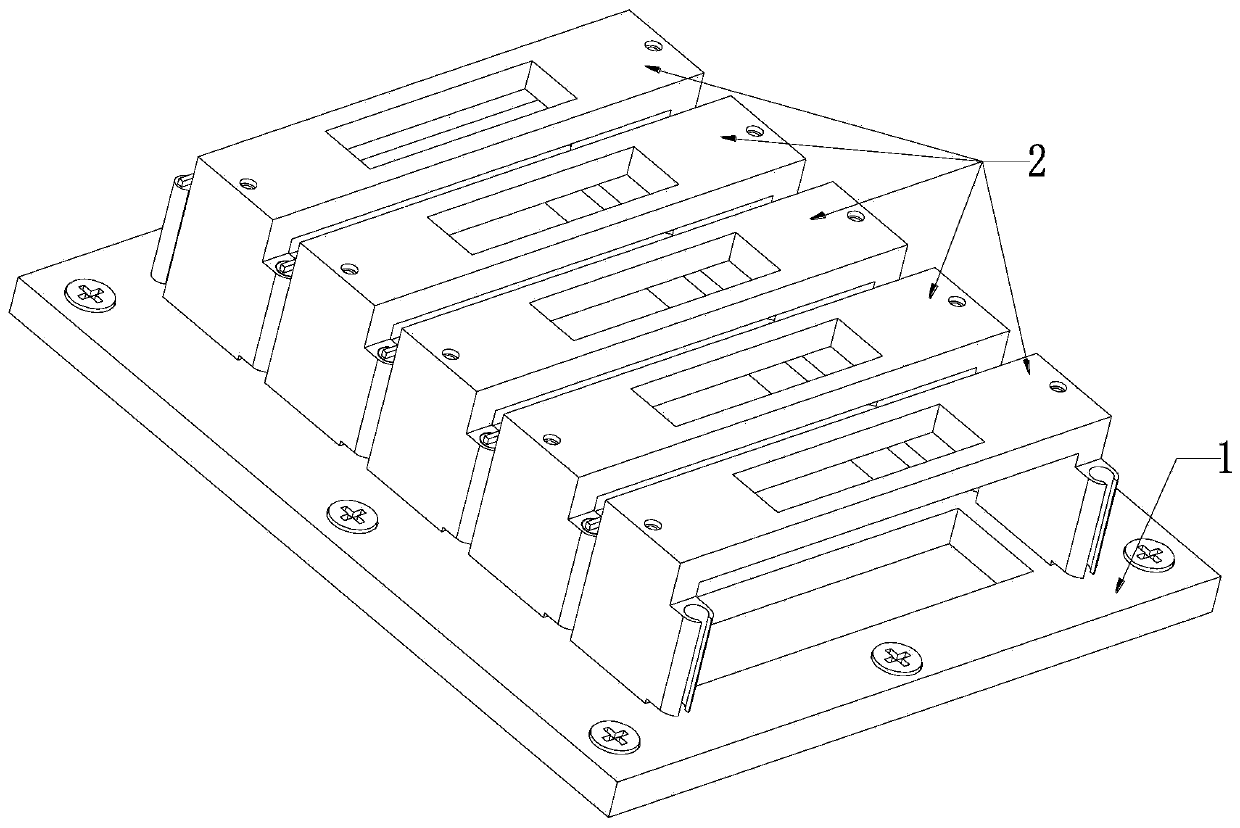
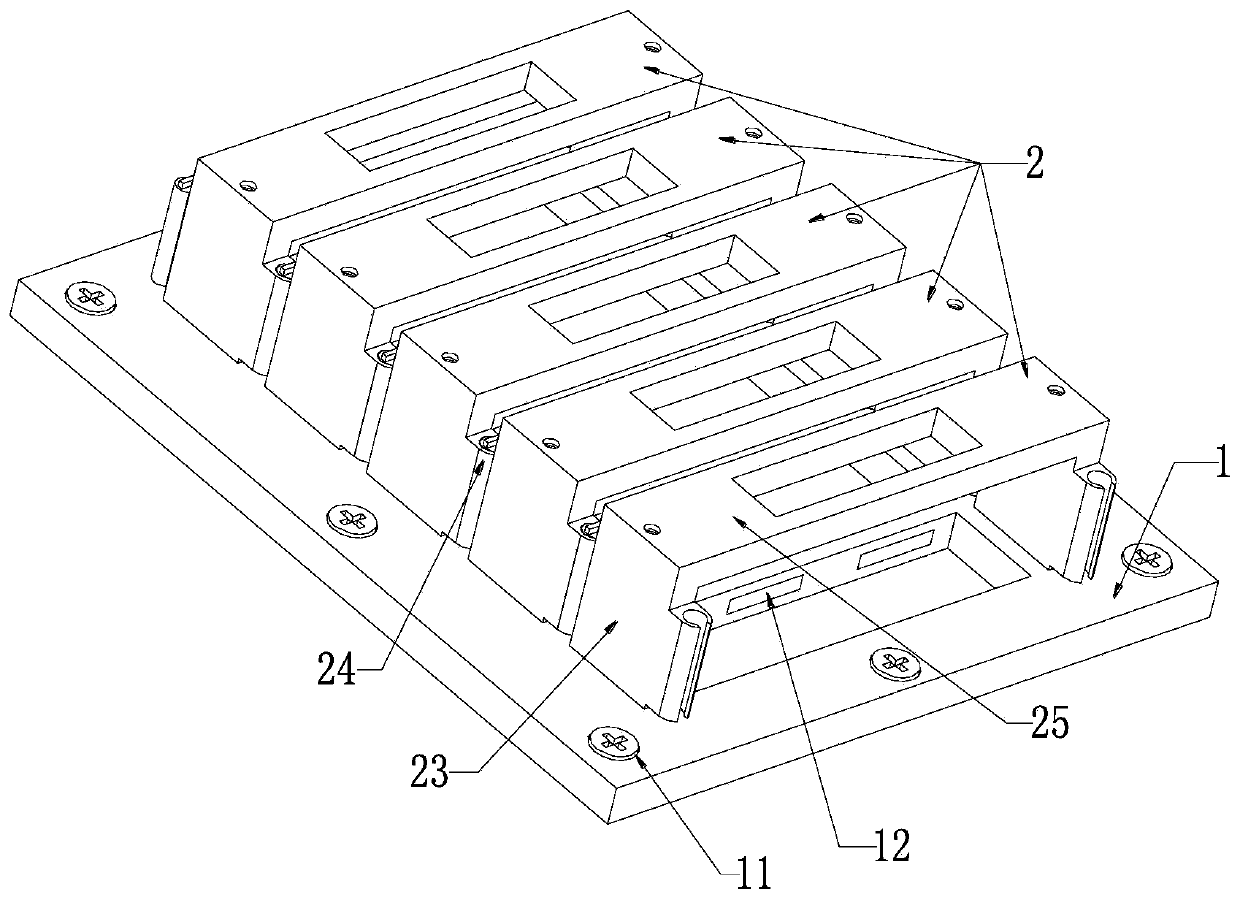
[0029] A power distribution cabinet busbar locking device, comprising a fixed plate 1 and a compression plate 2, the fixed plate 1 is installed on the power distribution cabinet through bolt connection, and a plurality of compression plates 25 are uniformly arranged on the fixed plate 1, wherein:

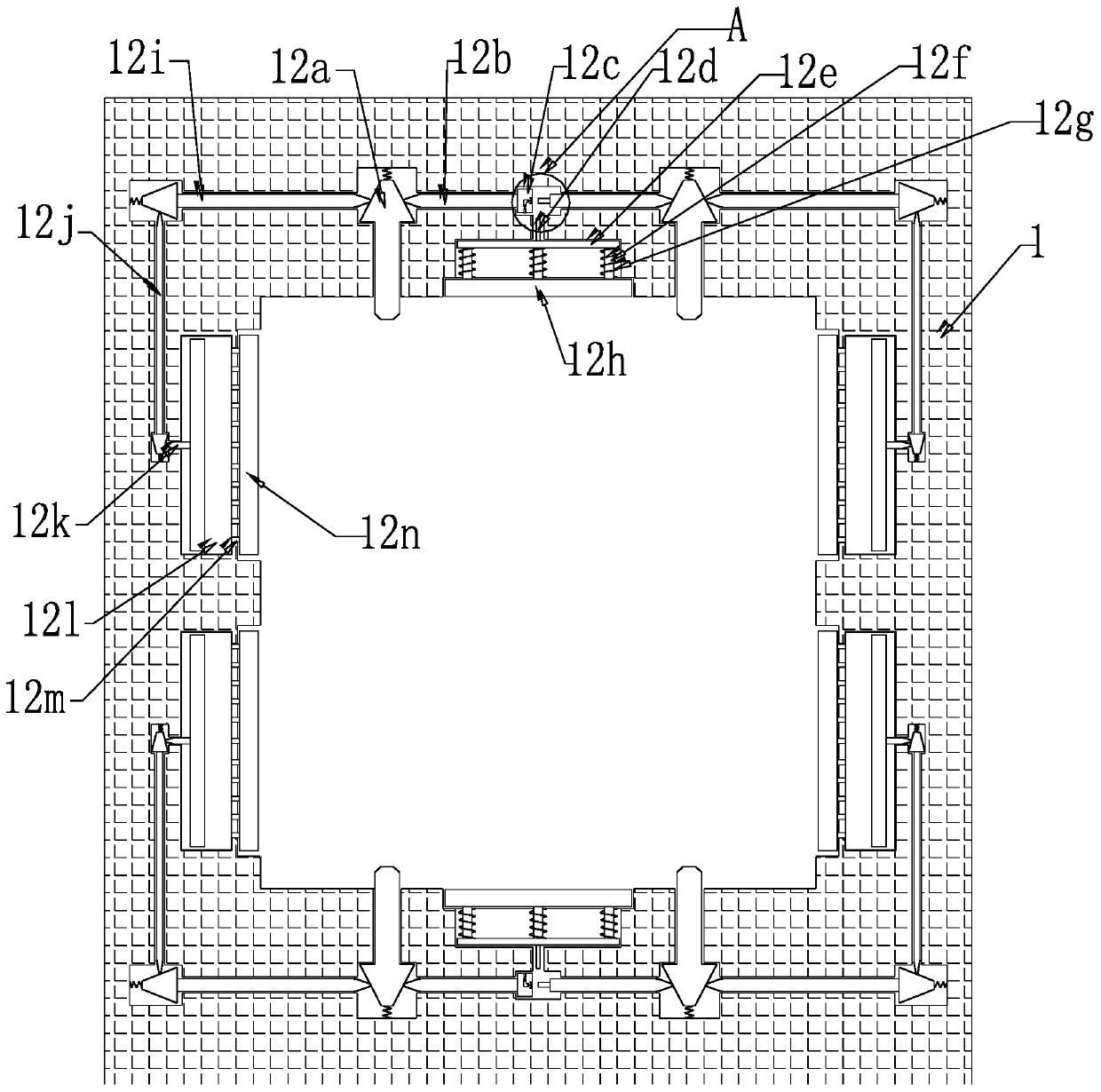
[0030] Screw holes cooperating with the screw holes on the power distribution cabinet are uniformly arranged around the fixed plate 1, locking screws 11 cooperating with each other are arranged inside the screw holes, and the center position of the fixed plate 1 is evenly provided with The through groove A used in conjunction with each other has a clamping mechanism 12 inside the through groove A, and blind grooves B are symmetrically arranged at the le...


PUM


Abstract

The invention relates to a bus locking device of a power distribution cabinet. The device comprises a fixed plate and pressing plates. The fixed plate is installed on the power distribution cabinet ina bolt connection mode. A plurality of pressing plates are uniformly arranged on the fixed plate. According to the invention, a the problems that when an existing power distribution cabinet bus is installed, due to the fact that installation is not firm enough, the existing power distribution cabinet bus is prone to falling off when encountering strong vibration, then large-scale power failure happens to a plant, and production efficiency is seriously affected can be solved; and b the problems that the pressing plates are often mounted at the rear end of the existing power distribution cabinet bus for packaging and mounting stability after mounting, so that when a problem occurs, the maintenance process is relatively complex, the whole plate needs to be dismounted for maintenance, and theworkload of workers is greatly increased can be solved.

Description

technical field [0001] The invention relates to the technical field of busbars, in particular to a busbar locking device for a power distribution cabinet. Background technique [0002] With the emergence of many high-rise buildings and large-scale workshops, the traditional cables used as transmission wires can no longer meet the requirements in the high-current transmission system, but the parallel use of multiple cables has brought a lot of inconvenience to the on-site installation and construction connections. Therefore, as a new type of distribution wire, the busbar is widely used in large factories and high-rise buildings, but the existing busbar is under installation There are still certain deficiencies in the process. [0003] The following problems often exist in the installation process of the existing power distribution cabinet busbar: a: When the existing power distribution cabinet is installed with the busbar, the installation is often not fast enough. A large-...

Claims


Application Information

Patent Timeline
Patent Type & Authority Applications(China)
IPC IPC(8): H02G5/06
CPCH02G5/06
Inventor 李小光焦文潭王璇段春霞杨涛
Owner ZHONGTIAN BROADBAND TECH
Learn More