
Passive trigger gas fire-extinguishing device for electric power machine room

A technology of fire extinguishing device and machine room, which is applied in fire rescue and other directions, can solve the problems of inability to automatically extinguish the fire and the fire extinguisher cannot be realized, and achieve the effect of increasing the exhaust area and the fire extinguishing area.

Inactive Publication Date: 2020-06-19
STATE GRID ZHEJIANG ELECTRIC POWER CO LTD JIAXING POWER SUPPLY CO +1
View PDF6 Cites 2 Cited by
  • Summary
  • Abstract
  • Description
  • Claims
  • Application Information

AI Technical Summary

Problems solved by technology

[0004] The present invention aims to solve the problem that the fire extinguisher cannot automatically extinguish the fire, and provides a passive trigger gas fire extinguishing device for the electric machine room. The present invention can quickly and effectively extinguish the fire spontaneously

Method used


Image

  • Passive trigger gas fire-extinguishing device for electric power machine room
  • Passive trigger gas fire-extinguishing device for electric power machine room
  • Passive trigger gas fire-extinguishing device for electric power machine room

Examples


Embodiment 1

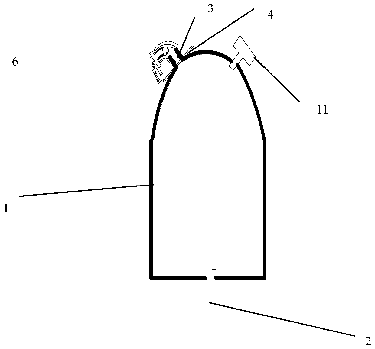
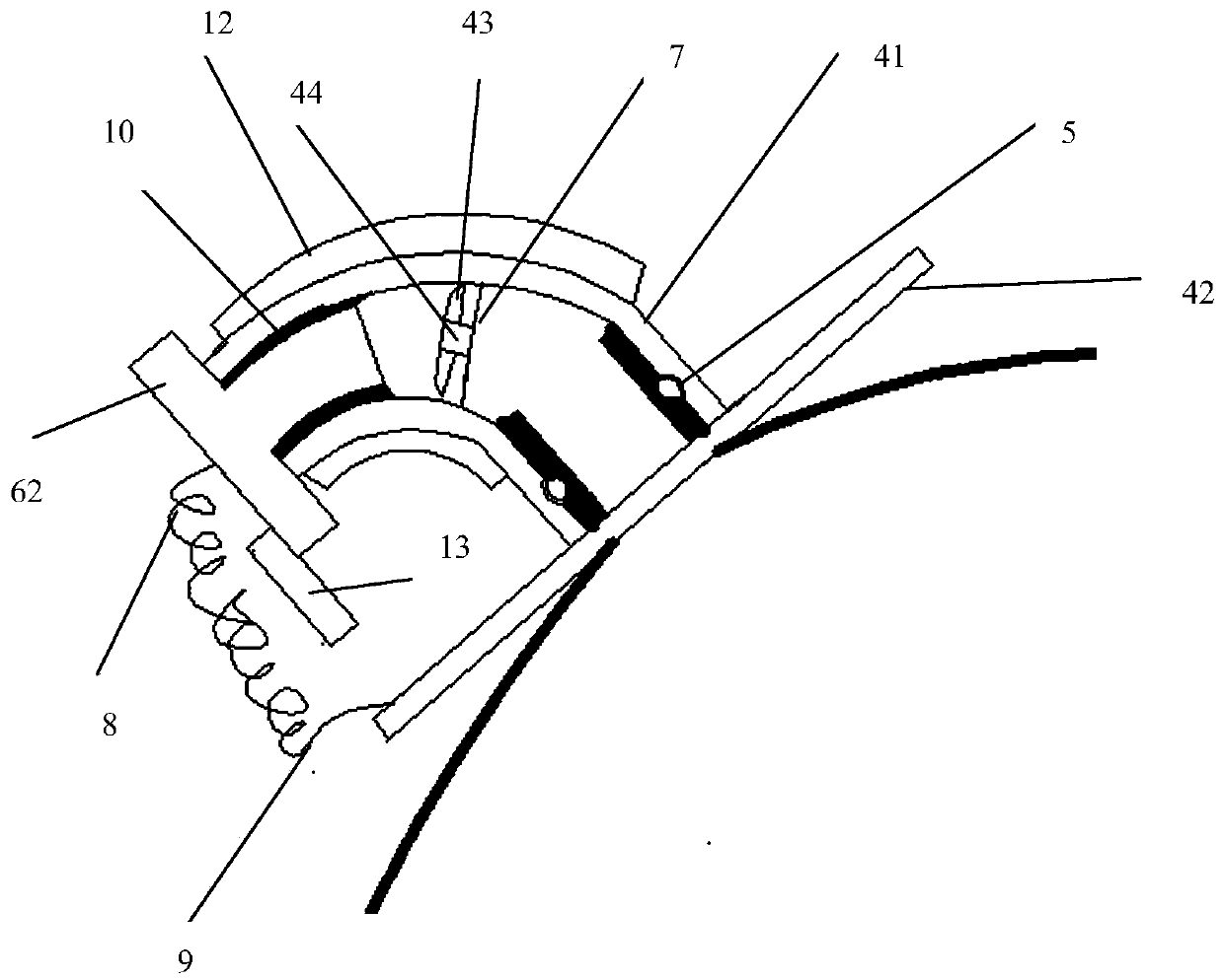
[0030] Embodiment 1, a passively triggered gas fire extinguishing device for an electric machine room, such as figure 1 , figure 2 and image 3 As shown, it includes a high-pressure gas tank 1, an intake valve 2 and an exhaust port 3. The top left side of the high-pressure gas tank 1 is provided with an exhaust port 3, and the exhaust port 3 is provided with a rotating nozzle 4, which is an elbow The rotary nozzle 4 is composed of two parts, the first part is an elbow 41, the second part is a rotary nozzle disc 42 fixedly connected with the elbow, the rotary blade 4 is provided with a rotating blade 43, and the rotating blade 43 rotates with the rotating shaft. Connect 44, the rotating shaft 44 is fixedly connected with the rotating seat 7, and the rotating seat 7 is as image 3 As shown, the rotating base 7 is fixedly connected with the rotating nozzle 4 . One end of the rotary nozzle is concentrically connected to the exhaust port of the high-pressure gas tank. A sealing...


PUM


Abstract

The invention relates to the field of fire extinguishers and discloses a passive trigger gas fire-extinguishing device for an electric power machine room. The passive trigger gas fire-extinguishing device for the electric power machine room comprises a high-pressure gas tank, an intake valve and an exhaust port. The left side of the top of the high-pressure gas tank is provided with the exhaust port, and a rotating sprayer is arranged at the exhaust port. The rotating sprayer is in an elbow shape. One end of the rotating sprayer is concentrically and rotationally connected with the exhaust port of the high-pressure gas tank, and a seal ring is arranged between the rotating sprayer and the exhaust port of the high-pressure gas tank. A metal plug is plugged into the other end of the rotary sprayer, a gap exists between the first end of the metal plug and an opening of the elbow of the rotary sprayer, and the gap is filled with a fusible material. The metal plug is connected with a connecting line. The bottom of the high-pressure gas tank is provided with the intake valve. One end of the intake valve is connected with a high-pressure flame retardant gas bin through a gas guide pipe, and the other end of the intake valve communicates with the high-pressure gas tank. The high-pressure gas tank is filled with high-pressure flame retardant gas. A pressure difference control valve capable of detecting the pressure difference between the inside and the outside of the high-pressure gas tank is arranged on the right side of the top of the high-pressure gas tank. The passive trigger gas fire-extinguishing device for the electric power machine room can rapidly and effectively conduct spontaneous fire extinguishing.

Description

technical field [0001] The invention relates to the field of fire extinguishers, in particular to a passive trigger gas fire extinguishing device for an electric machine room. Background technique [0002] The power computer room plays a very important role in the power system. The equipment in the computer room of the electronic information system is complex and asset-intensive. It is necessary to ensure the normal operation of electronic equipment. Large and static electricity, etc. Once a fire occurs in the computer room, it will cause major losses and chaos in the order of power dispatching. Therefore, the fire protection system is an indispensable guarantee for the power computer room. [0003] For example, a "container valve and fire extinguishing device" disclosed in Chinese patent literature, its publication number is CN109568865A, this invention provides a container valve and a fire extinguishing device, wherein the container valve includes a valve body and a valve ...

Claims


Application Information

Patent Timeline
IPC IPC(8): A62C31/03A62C31/05A62C37/11A62C37/40
CPCA62C31/03A62C31/05A62C37/11A62C37/40
Inventor 唐锦江杨京才郁哲亮陆恩灏陈杰光沙磊康超懿黄沈海娄竞
Owner STATE GRID ZHEJIANG ELECTRIC POWER CO LTD JIAXING POWER SUPPLY CO
Learn More