

Lamination of permanent magnet motor stator core
A stator core and permanent magnet motor technology, applied in magnetic circuits, electrical components, electromechanical devices, etc., can solve the problems of potential safety hazards and the same cut size, and achieve the effect of improving safety and service life
- Summary
- Abstract
- Description
- Claims
- Application Information
AI Technical Summary
Problems solved by technology
Method used
Image

Examples
Embodiment Construction
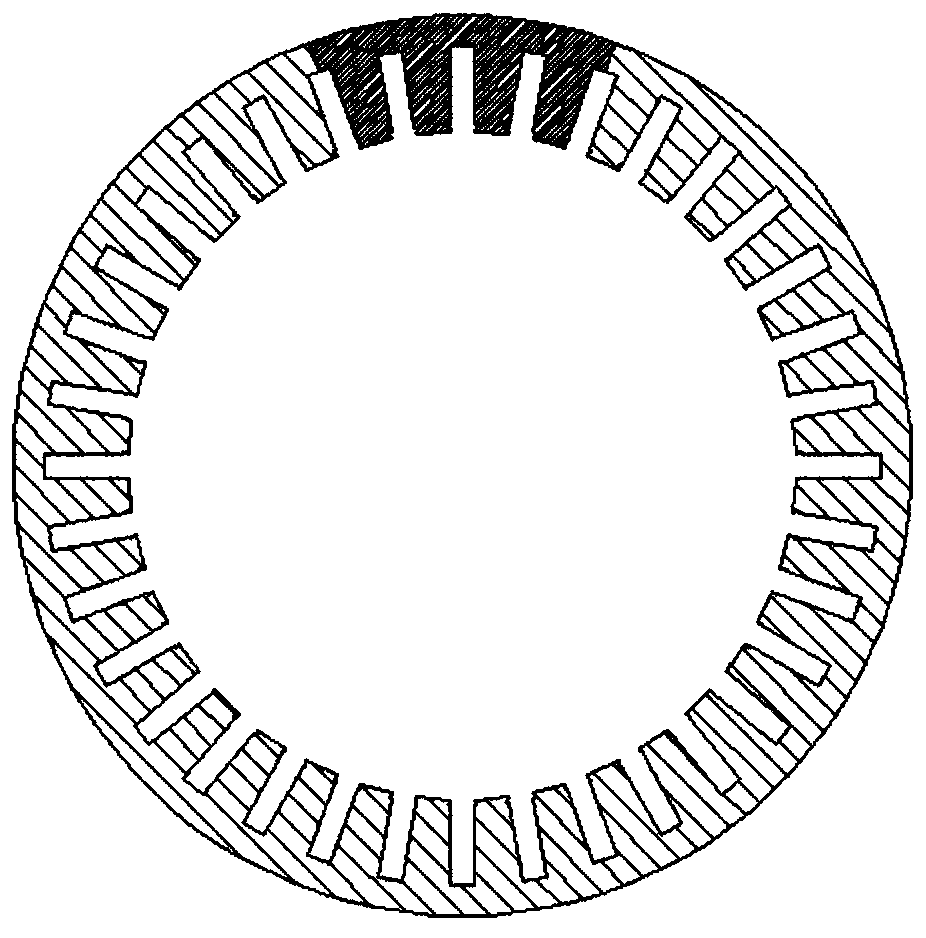
[0022] The stator iron core of the permanent magnet motor of the present embodiment is formed by stacking a plurality of annular laminations, and the annular laminations are an annular structure (such as figure 1 As shown, the shaded part is a stator segment), the stator segment is provided with a stator slot 5 with a slot depth of H1, and both sides of the stator slot 5 are provided with triangular cutouts for placing slot wedges to prevent the conductors in the stator slot 5 from protruding .
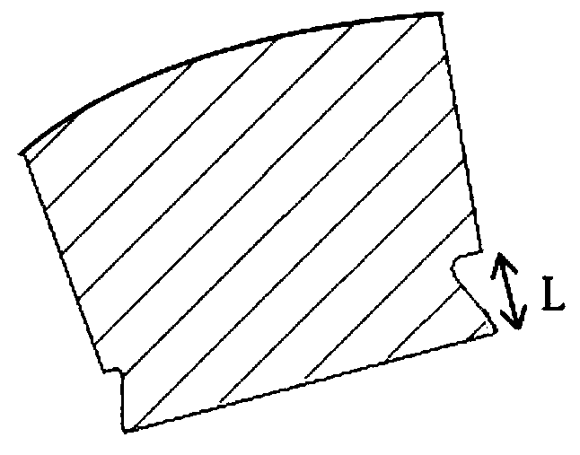
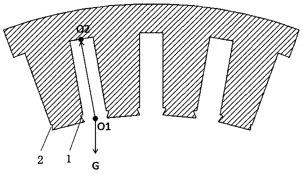
[0023] When in use, the annular laminations are placed vertically, and the cutouts on the annular laminations include cutouts A1, B2, C3 at the notch of the stator slot 5, and cutout D4 in the middle of the stator slot 5.
[0024] The radial dimension L of the notch at the notch is as follows: the radial dimension of the notch A1 is larger than the notch C3, the radial dimension of the notch C3 is larger than the notch B2, and the midpoint of the circumferential length of the notch of...
PUM
 Abstract
Description
Claims
Application Information