Sand homogenizing device used before tile paving for building construction

A technology for building construction and paving tiles, which is applied to buildings, building structures, roads, etc., can solve problems such as inability to achieve depth, shallow pits, unified adjustment, etc., to achieve convenient operation, increase friction coefficient, increase The effect of the contact surface

Inactive Publication Date: 2020-06-23
王功起
View PDF9 Cites 0 Cited by
  • Summary
  • Abstract
  • Description
  • Claims
  • Application Information

AI Technical Summary

Problems solved by technology

[0003] At present, the smoothing of sand before laying floor tiles depends entirely on the experience of the operators. However, due to errors in the manual operation process, the sand layer in some places will be thicker and the sand layer in some places will be thinner or there will be shallow pits. In the process of laying, it is necessary to constantly replace the sand equalizing tools, and the uniform adjustment of the depth cannot be achieved during the process of sand equalizing, which will affect the later laying

Method used


Image

  • Sand homogenizing device used before tile paving for building construction
  • Sand homogenizing device used before tile paving for building construction
  • Sand homogenizing device used before tile paving for building construction

Examples


Embodiment 1

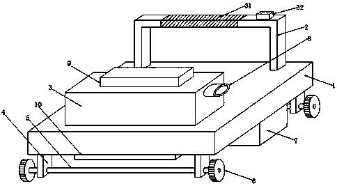
[0035] Example one, such as figure 1 As shown, according to an embodiment of the present invention, a sand leveling device for building construction before paving tiles includes a base 1, a handle 2 is provided on the upper side of the base 1, the roller 6 is a rubber wheel, and the upper end of the handle 2 is sleeved Anti-slip cover 31, one side of the anti-slip cover 31 and the upper end of the handle 2 is provided with a control switch 32, the upper end of the base 1 is provided with a box 3 on the other side, the lower end of the base 1 is surrounded by support rods 4, two sets of supports A movable shaft 5 is interspersed between the rods 4, the two ends of the movable shaft 5 are sleeved with rollers 6, the lower end of the base 1 is located between the two sets of movable shafts 5, and an adjusting device 7 is provided. The lower end of the box body 3 is located on the base The bottom of 1 is provided with a discharge port 8, the upper end of the box body 3 is provided w...

Embodiment 2

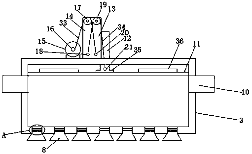
[0037] Example two, such as Figure 2-4 As shown, on the basis of the first embodiment, the present invention provides a technical solution: the pressing device 9 includes a pressing plate 11 located at the inner upper end of the box 3, and the upper end of the pressing plate 11 is provided with a movable rod 12, the movable rod A movable rod 13 is provided on one side of the one 12, and a fixed rod 14 is provided on the side of the movable rod 13 away from the movable rod 12. The movable rod 12 and the movable rod 13 penetrate the upper end of the box 3, and the fixed rod 14 Located at the upper end of the box body 3, the fixed rod 14 is far away from the movable rod two 13 and is provided with a motor 15 at the upper end of the box body 3. The output shaft of the motor 15 is provided with a rotating wheel 16, and the fixed rod 14 is provided with a side upper end Pulley one 17, fixed pole 18 is provided at the lower end of one side of fixed rod 14, pulley two 19 is provided at...

Embodiment 3

[0039] Example three, such as Figure 2-4 As shown, on the basis of the first and second embodiments, the present invention provides a technical solution: the rotating wheel 16, the pulley one 17, and the fixed column two 20 are connected by a draw rope 33, and the fixed column 18, the pulley The two 19 and the fixed column three 21 are connected by a draw rope two 34. The upper end of the pressure plate 11 and the two sides of the movable rod 12 are provided with counterweights 35, and the pressure plate 11 and the lower end of the movable rod 12 are bolted 36 fixed.

[0040] By setting the pull rope 33, the work of the motor 15 can realize the up and down movement of the movable rod two 13. By setting the pull rope 34, the work of the motor 15 can realize the movement of the upper end of the movable rod 12, by setting the counterweight 35 , Increase the weight of the pressure plate 11, facilitate the downward movement of the pressure plate 11, complete the rapid discharge of mo...


PUM


Abstract

The invention discloses a sand homogenizing device used before tile paving for building construction. The device comprises a base, one side of the upper end of the base is provided with a handle, theother side of the upper end of the base is provided with a box, supporting rods are arranged on the periphery of the lower end of the base, movable shafts are inserted between the two sets of supporting rods, and the two ends of each movable shaft are sleeved with rollers. An adjusting device is arranged at the lower end of the base and between the two movable shafts, and discharge openings are formed in the lower end of the box and in the bottom of the base. The upper end of the box is provided with an extrusion device, and the two sides of the box are each provided with a feed inlet. The extrusion device comprises a pressing plate located at the upper end in the box, a first movable rod is disposed at the upper end of the pressing plate, a second movable rod is disposed on one side of the first movable rod, and a fixed rod is arranged on the side, away from the first movable rod, of the second movable rod. The first movable rod and the second movable rod penetrate through the upper end of the box, the fixed rod is located at the upper end of the box, and a motor is arranged on the side, away from the second movable rod, of the fixed rod and located at the upper end of the box. Anoutput shaft of the motor is provided with a rotary wheel.

Description

Technical field [0001] The invention relates to the field of construction, and in particular to a sand leveling device before floor tiles for construction. Background technique [0002] At present, in the process of building construction (especially house decoration, road paving, etc.), it is necessary to pre-lay a sand layer on the base surface, and then lay tiles or floor tiles on the surface of the sand layer. In order to ensure that the laid tiles or floor tiles are flat, it is necessary to Smooth and pre-even the sand layer. [0003] At present, the leveling of sand before laying the floor tiles depends entirely on the experience of the operators. However, due to errors in the manual operation, the sand layer in some places will be thicker and the sand layer in some places will be thinner or there are shallow pits, and the floor tiles There are a variety of sizes. During the laying process, the sand leveling tools need to be replaced constantly. In the process of sand levelin...

Claims


Application Information

Patent Timeline
Patent Type & Authority Applications(China)
IPC IPC(8): E04F21/24E01C19/48
CPCE01C19/4866E01C19/4873E04F21/241E04F21/244
Inventor 王功起秦承良施平
Owner 王功起
Why Eureka
Try Eureka