Bidirectional separation and reunion structure for door lock, door lock and antitheft door

A two-way clutch and door lock technology, applied in the field of locks, can solve the problems that the rear handle is easily locked by the motor, and the door lock cannot be opened, and achieves the effect of simplifying the difficulty of installation and manufacturing of parts, and improving adaptability

Pending Publication Date: 2020-06-23
WONLY SECURITY & PROTECTION TECH CO LTD
View PDF1 Cites 2 Cited by
  • Summary
  • Abstract
  • Description
  • Claims
  • Application Information

AI Technical Summary

Problems solved by technology

[0006] Therefore, the technical problem to be solved by the present invention is that when the motor of the electronic lock in the prior art fails, the user can only switch the door lock by rotating the rear handle. Rotating the handle is easy to be locked by the motor, resulting in the problem that the door lock cannot be opened

Method used


Image

  • Bidirectional separation and reunion structure for door lock, door lock and antitheft door
  • Bidirectional separation and reunion structure for door lock, door lock and antitheft door
  • Bidirectional separation and reunion structure for door lock, door lock and antitheft door

Examples


Embodiment 1

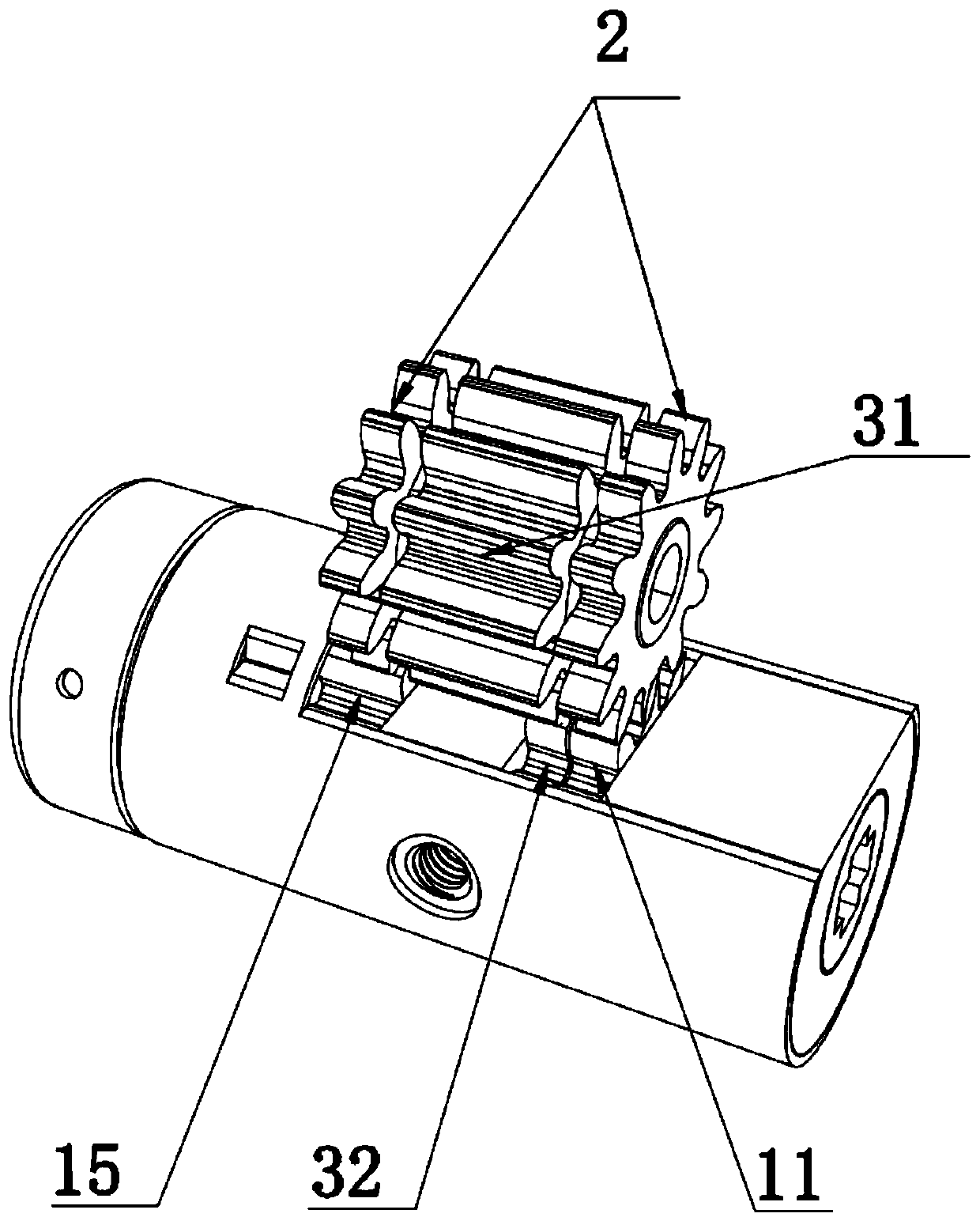
[0076] This embodiment provides a security door, such as Figure 1 to Figure 8 As shown, including: a door lock, and a door body on which the door lock is installed. Among them, the door lock includes: a lock box, a telex mechanism and a two-way clutch structure. Wherein, the lock box is provided with a linkage switch dial 2; the telex mechanism has a telex driver and a telex dial 32, and the telex driver drives the telex dial 32 to rotate; the bidirectional clutch structure is connected to the linkage switch dial 2 and the telex dial 32; Between the thumb wheel 32. For example, the teletype drive is a motor, and the motor and the teletype dial 32 are connected and driven through a transmission gear 31 .

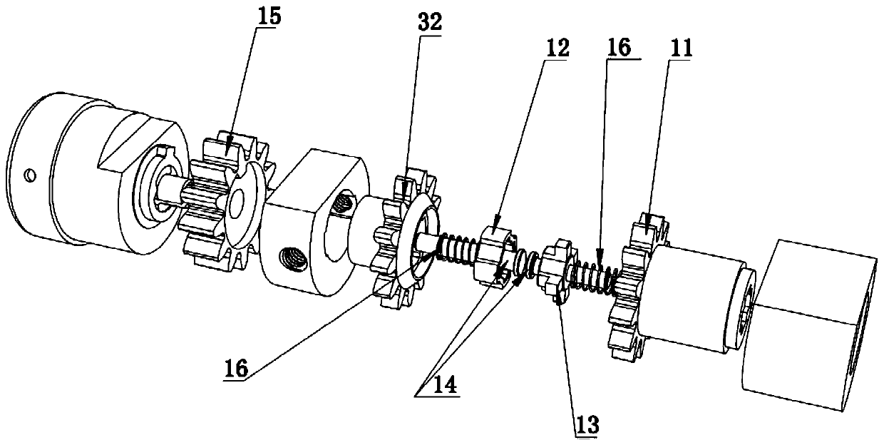
[0077] Such as figure 2 with Figure 4 As shown, the above-mentioned two-way clutch structure for a door lock includes: a linkage 14 , a driving dial 11 , a connecting dial 15 , an electric clutch 12 and a rotating clutch 13 . Wherein, the driving dial 11 is arranged o...

Embodiment 2

[0092] Compared with the anti-theft door provided in Embodiment 1, the anti-theft door provided in this embodiment differs in that: the driving dial 11 and the connecting dial 15 are arranged on the same side of the teletype dial 32, as long as the external All can realize driving dial 11 and connecting dial 15 to rotate when transmission member stretches into.

[0093] Furthermore, the connecting dial 15 may not be provided, and the external transmission parts on both sides may be directly connected to the driving dial 11 after the clutch parts are in the clutch state. For example, when the two clutch parts are completely separated, the external transmission part is mutually limited with the driving dial 11 on both sides of the two-way clutch structure, so that when the external transmission part rotates, it drives the linkage switch dial 2 to rotate and then drives the door lock Opening and closing.

Embodiment 3

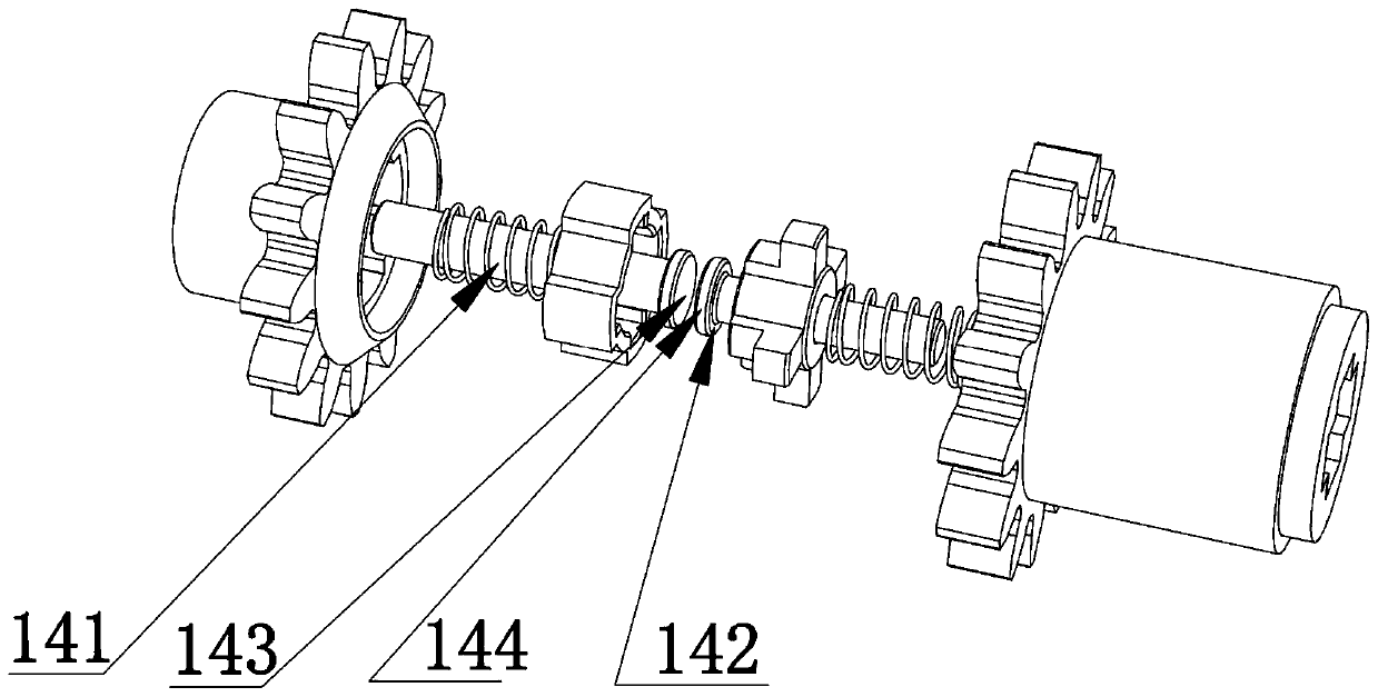
[0095] Compared with the anti-theft door provided in Embodiment 1 or 2, the anti-theft door provided in this embodiment differs in that: in this embodiment, one linkage 14 can be provided, and the linkage 14 is provided in the through The cylindrical rod in the hole 321 has a connecting flange 144 installed on the connecting part 141, and both sides of the flange are abutting parts 142, which are respectively abutted against the electric clutch part 12 and the rotating clutch part 13. On the facing wall, actuation is likewise possible. As a further modification of this embodiment, the door lock may not be provided with the linkage 14, and it is sufficient to separate the two clutches only through the driving of the external transmission.


PUM


Abstract

The invention discloses a bidirectional separation and reunion structure for a door lock, the door lock and an antitheft door. The bidirectional separation and reunion structure comprises a driving thumbwheel and a pair of separation and reunion pieces capable of being separably inserted into each other. The driving thumbwheel is opposite to a telex thumbwheel. The driving thumbwheel is connectedbetween the telex thumbwheel and a linkage on-off thumbwheel. The driving thumbwheel is in linkage with the linkage on-off thumbwheel so that unlocking or locking can be realized. One of the pair of separation and reunion pieces is a telex separation and reunion piece slidingly arranged in the telex thumbwheel, and the other of the pair of separation and reunion pieces is a rotating separation andreunion piece slidingly installed in the driving thumbwheel. The driving thumbwheel is not affected by the locking of the telex thumbwheel when the two separation and reunion pieces are at a separated separation and reunion state, the manual unlocking and locking of the door lock are realized through an external transmission piece directly by controlling the rotation of the linkage on-off thumbwheel, and the problem that an electric door lock cannot be opened when a motor is locked is avoided.

Description

technical field [0001] The invention relates to the technical field of locks, in particular to a bidirectional clutch structure for a door lock, a door lock and an anti-theft door. Background technique [0002] The existing electric door lock consists of two components, a lock box and an electric lock cylinder. The lock box is embedded between the inner and outer surfaces of the door panel. The electric lock cylinder is connected to the lock box. The motor directly drives the dial to rotate, and the dial then drives the latch in the lock box. [0003] Chinese patent document CN208918430U discloses a kind of electronic lock with automatic manual operation, which includes an output shaft, a transmission lock cylinder, a motor, a first clutch structure, a front handle and a rear handle of a second clutch structure. Wherein, the rear handle is connected to the output shaft, and the output shaft is connected to the motor through the first clutch structure, and the output shaft i...

Claims


Application Information

Patent Timeline
IPC IPC(8): E05B47/00E05B15/00E05B17/22E06B5/11
CPCE05B15/00E05B17/22E05B47/0012E05B2047/0026E06B5/11
Inventor 支崇铮
Owner WONLY SECURITY & PROTECTION TECH CO LTD
Why Eureka
Try Eureka