Aircraft active load reduction structure based on cavitator

A technology of active load reduction and aircraft, applied in the direction of motor vehicles, hydrodynamic characteristics/hydrostatic characteristics, underwater operation equipment, etc., can solve the problems of unacceptable weight, space, performance cost, etc.

Inactive Publication Date: 2020-06-26
NORTHWESTERN POLYTECHNICAL UNIV
View PDF8 Cites 10 Cited by
  • Summary
  • Abstract
  • Description
  • Claims
  • Application Information

AI Technical Summary

Problems solved by technology

This method takes advantage of the characteristics of the missile itself to carry fuel and obtains local materials, which can provide protection for the missile entering the water at high speed; however, when it is applied to an underwater vehicle, it is necessary to place a complete set of gas generation and injection systems inside the already very compact vehicle. The resulting weight, space, and performance costs are unacceptable

Method used


Image

  • Aircraft active load reduction structure based on cavitator
  • Aircraft active load reduction structure based on cavitator
  • Aircraft active load reduction structure based on cavitator

Examples


Embodiment Construction

[0018] The present invention will now be further described in conjunction with the embodiments and drawings:

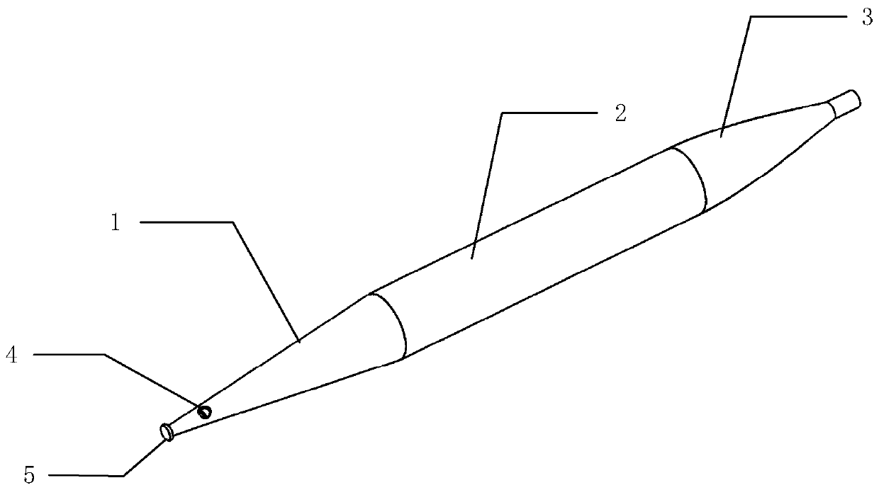
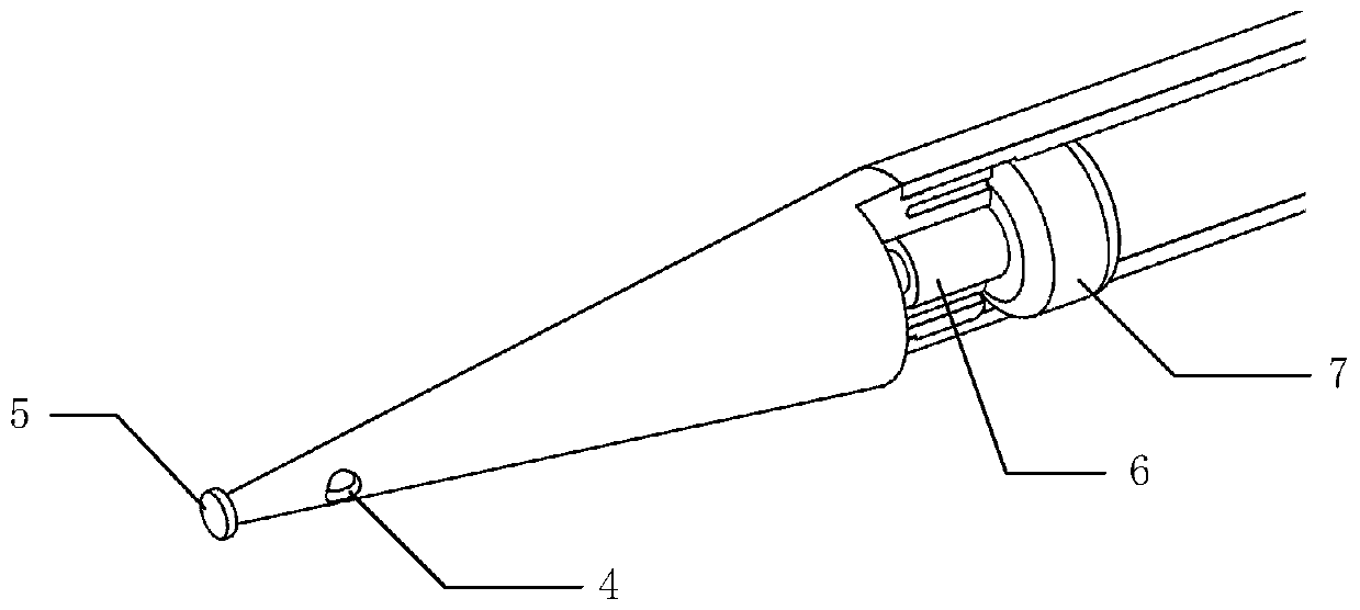
[0019] As attached figure 1 As shown, the application object of the present invention is an underwater vehicle. Generally, the underwater vehicle can be divided into the head of the vehicle 1, the middle section of the vehicle 2, and the tail section of the vehicle 3. In the present invention, an active load reduction system is designed in the head 1 of the aircraft. The active load reduction system includes an air jet hole 4, a cavitation device 5, a jet on-off valve 6 and a high-pressure gas cylinder 7. The active load shedding system occupies a small space and does not have a big impact on other parts in the head of the aircraft. The cavitator 5 is located at the top of the head 1 of the aircraft, and is a disc-shaped structure with an acute edge. Its function is to guide the area behind the cavitator to form a smooth and smooth package cavity. The supercavitation g...


PUM


Abstract

The invention relates to an aircraft active load reduction structure based on a cavitator. A gas injection flow channel is designed in the head of an aircraft, and gas flow injection holes are designed in the outer side face of the aircraft. A cavitator is designed at the top end of the head of the aircraft, the cavitator is of a disc-shaped structure with an acute angle edge, and ventilation is conducted through airflow jet holes behind the acute angle structure to form supercavitation bubbles surrounding an object. A gas injection on-off valve is located behind the interior of the head of the aircraft, is connected with an injection flow channel and a high-pressure gas bottle and is directly controlled by an aircraft gas injection control system to control on-off of air flow. And the high-pressure gas cylinder is positioned at the rear part of the gas injection on-off valve and stores all high-pressure gas required for generating the supercavity. High-pressure compressed air serves as a ga source, and compared with fuel gas injection load reduction, the system is more compact and smaller and is more suitable for being applied to small and medium-sized underwater vehicles.

Description

Technical field [0001] The invention relates to the field of high-speed water entry and load reduction of an aircraft, in particular to an active load reduction structure of an aircraft based on a cavitator. Background technique [0002] The underwater vehicle will inevitably undergo a process of entering the water after being assisted by a rocket or being launched by an aircraft. The process of entering the water is a fast and short transient process, during which a huge impact load will be generated on the aircraft. If the load is not reduced by some technical means, it will cause obvious or potential damage to the shape, structure, and components of the aircraft. [0003] Supercavitation technology is a very effective method of load reduction. Russia first proposed the concept of an underwater supercavitation vehicle. By enclosing the vehicle in a cavitation, the vehicle is isolated from the water, thereby greatly reducing the resistance of the vehicle under water. The basic ...

Claims


Application Information

Patent Timeline
Patent Type & Authority Applications(China)
IPC IPC(8): B63G8/00B63B1/38
CPCB63B1/38B63B2001/382B63G8/001B63G2008/002Y02T70/10
Inventor 施瑶潘光华扬宋保维黄桥高赵海瑞
Owner NORTHWESTERN POLYTECHNICAL UNIV
Why Eureka
Try Eureka