A locking component of a pneumatic measuring device

A technology of locking components and pneumatic measurement, which is applied in the direction of measuring devices, brake parts, and fluid devices, etc., can solve problems such as damage, unstable measurement of measuring machines, and affect the accuracy of measurement data, so as to achieve the effect of stable use

Active Publication Date: 2021-07-23
上海顺裕机电技术发展有限公司
View PDF10 Cites 0 Cited by
  • Summary
  • Abstract
  • Description
  • Claims
  • Application Information

AI Technical Summary

Problems solved by technology

[0004] When the measuring machine in the above patent is in use, if the gas supply equipment fails or the gas is exhausted, the elastic body will quickly retract, resulting in unstable measurement of the measuring machine, and even damage. The structure can lock the measuring state of the measuring machine when the gas supply equipment is faulty or the gas is exhausted and the elastic body is quickly retracted; however, when locked, the measuring machine will experience the state changes of locked, free, and locked, so that the measuring machine is locked. Oscillation occurs during the process, which greatly affects the accuracy of the measurement data

Method used


Image

  • A locking component of a pneumatic measuring device
  • A locking component of a pneumatic measuring device
  • A locking component of a pneumatic measuring device

Examples


Embodiment Construction

[0032] The present invention will be described in detail below in conjunction with the accompanying drawings and embodiments.

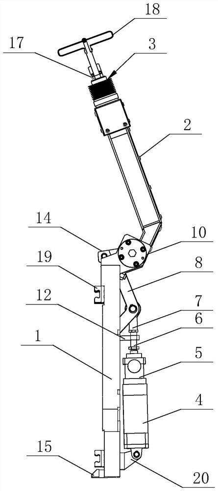
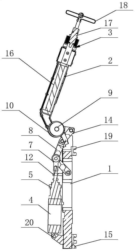
[0033] A locking assembly for a pneumatic measuring device such as figure 1 and figure 2 As shown, it includes sliding arm 1, rotating arm 2 and measuring head 3. A bracket 20 is provided at the middle position on the upper surface of one end of the sliding arm 1 , and a cylinder 4 is installed on the bracket 20 along the length direction of the sliding arm 1 , and the opening of the cylinder 4 points to the other end of the sliding arm 1 . A push-pull rod 5 is arranged inside the cylinder 4, and the push-pull rod 5 can slide parallelly along the cavity direction of the cylinder 4. When the gas is charged into the cylinder 4, the push-pull rod 5 slides toward the opening direction of the cylinder 4, and when the gas is discharged from the cylinder 4, the push-pull rod 5 slides toward the opposite direction of the cylinder 4 opening. The end of the...


PUM


Abstract

The invention relates to the technical field of measuring devices, and discloses a locking assembly of a pneumatic measuring device, which includes a sliding arm, the sliding arm is provided with a bracket, the bracket has a cylinder, the cylinder has a built-in push-pull rod, the push-pull rod is provided with a connecting shaft, and the sliding arm is provided with Rotating shaft, there is a rotating arm on the rotating shaft, the rotating arm is equipped with a measuring head, one end of the sliding arm is connected with the sliding arm, and the other end is connected with the rotating shaft, the transmission chain is bent to the side of the cylinder, and the bending part is provided with a transmission rod, connecting the shaft It is connected with the transmission rod, and the connecting shaft is provided with a brake, and the brake is fixedly connected with a holding rod, and the holding rod is fixed on the sliding arm; the sliding arm is provided with a support block, and the end of the support block contacting the rotating shaft is connected with an airbag. The inside of the airbag is filled with reserved gas; during the self-locking process, the airbag makes the resistance between the top of the pole and the connecting shaft increase smoothly and linearly until the locking is completed, and the airbag makes the use of the measuring device more stable.

Description

technical field [0001] The invention relates to the technical field of measuring devices, more specifically, it relates to a locking assembly of a pneumatic measuring device. Background technique [0002] Pneumatic is to use compressed air as the power source to drive the machine to complete the expansion and contraction or rotation. Pneumatic devices have the advantages of simple structure, light weight, simple installation and maintenance, low pressure level, and safer use than hydraulic systems. [0003] The Chinese utility model patent with the patent notification number CN206504712U discloses a pneumatic measuring assembly and a measuring machine including the pneumatic measuring assembly, which are helpful for automatic measurement of workpiece dimensions. The pneumatic measurement assembly includes a measuring head installed on the main body of the measuring machine and an adjustment mechanism for connecting the main body of the measuring machine with the measuring h...

Claims


Application Information

Patent Timeline
Patent Type & Authority Patents(China)
IPC IPC(8): F16M11/04F16M11/10F16M11/18F16M11/42F16D49/16F16D65/06F16D63/00F16D65/02F16F15/023G01B13/00
CPCF16D49/16F16D63/00F16D65/02F16D65/06F16F15/0232F16M11/04F16M11/10F16M11/18F16M11/2085G01B13/00
Inventor 袁松涛陈革新
Owner 上海顺裕机电技术发展有限公司
Why Eureka
Try Eureka