Cleaning device for medical apparatuses and instruments

A technology for cleaning devices and medical devices, applied in the field of medical devices, can solve problems such as poor cleaning effect, and achieve the effect of increasing the cleaning effect

Inactive Publication Date: 2020-06-30
程仁生
View PDF0 Cites 1 Cited by
  • Summary
  • Abstract
  • Description
  • Claims
  • Application Information

AI Technical Summary

Problems solved by technology

[0003] Most medical devices need to be cleaned before and after use, but the existing cleaning devices are usually immersion static cleaning of medical devices, and the cleaning effect is not good

Method used


Image

  • Cleaning device for medical apparatuses and instruments
  • Cleaning device for medical apparatuses and instruments
  • Cleaning device for medical apparatuses and instruments

Examples


Embodiment 1

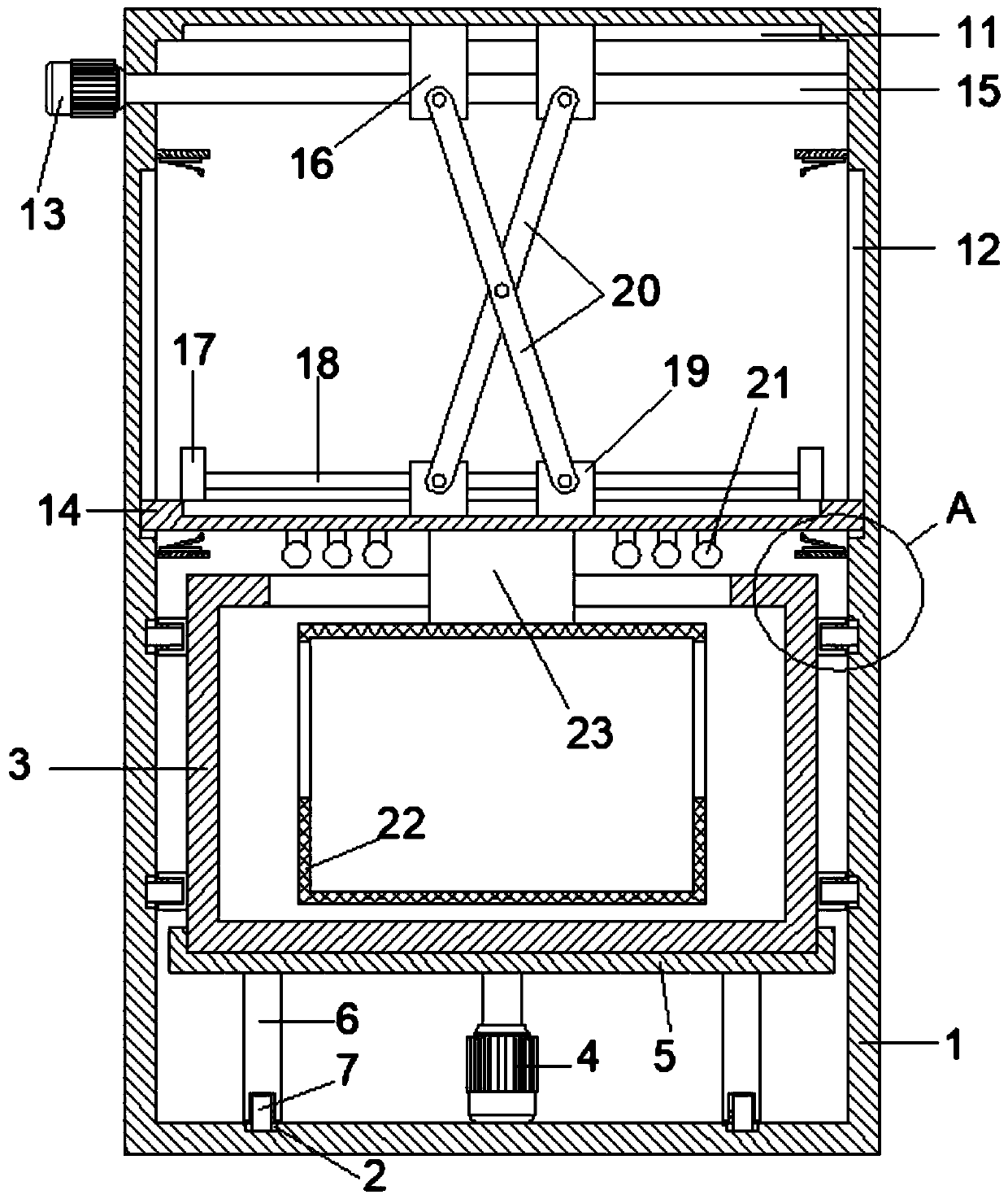
[0021] Such as Figure 1-2 , a medical instrument cleaning device, cleaning box 1 and instrument placement assembly, a lifting device is arranged above the inside of the cleaning box 1, the instrument placement assembly is arranged on the lifting device, and the inside of the cleaning box 1 A dynamic liquid storage tank assembly is provided below, and the bottom of the cleaning tank 1 is provided with an annular chute 2. The dynamic liquid storage tank assembly includes an open liquid storage tank 3 and is fixedly installed on the bottom of the cleaning tank 1 The motor 4, the output end of the motor 4 is fixedly installed with a connecting plate 5, the connecting plate 5 is fixedly installed at the bottom of the liquid storage box 3, and the bottom of the connecting plate 5 is evenly arranged with a number of support columns 6 along the circumferential direction, The bottom of the support column 6 is rotatably installed with a roller 7 that cooperates with the annular chute 2...

Embodiment 2

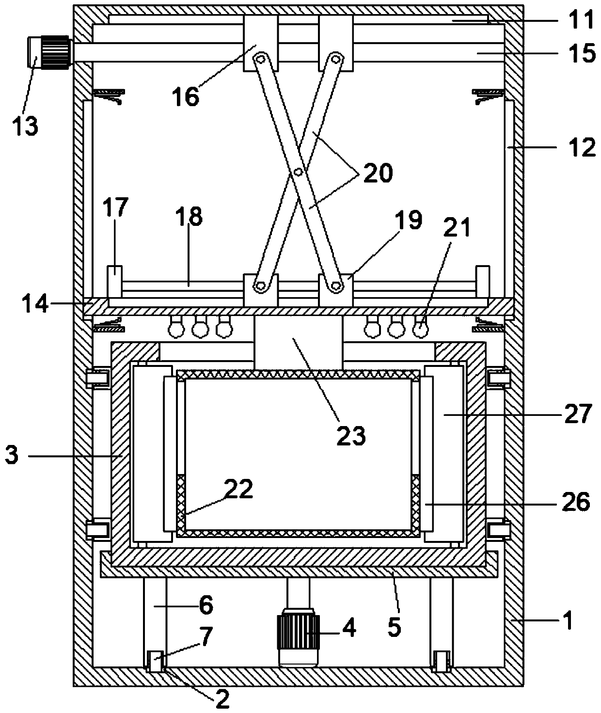
[0027] Such as image 3 , the present embodiment is further improved on the basis of the embodiment, the improvement is that: a number of evenly distributed baffles 26 are fixedly installed on the outer wall of the placement net cover 22, and the inner wall of the liquid storage box 3 is along the circumference A number of elastic steel sheets 27 are evenly arranged, and the blocking sheet 26 and the elastic steel sheet 27 are interference fit; by setting the blocking sheet 26 and the elastic steel sheet 27, the liquid storage box 3 drives the elastic steel sheet 27 to rotate during the rotation process. , The blocking piece 26 is in interference fit with the elastic steel sheet 27, so that the elastic steel sheet 27 hits the blocking piece 26 when rotating, thereby affecting the fluctuation of the cleaning liquid in the liquid storage box 3, and further improving the cleaning effect.

[0028] The working principle of this embodiment is: by arranging the baffle 26 and the elas...


PUM


Abstract

The invention discloses a cleaning device for medical apparatuses and instruments. The cleaning device for the medical apparatuses and instruments comprises a cleaning box body and an apparatus and instrument placement assembly, wherein a lifting device is arranged at an upper part in the cleaning box body; a dynamic liquid storage box assembly is arranged at a lower part in the cleaning box body;an annular slide groove is formed in the bottom of the cleaning box body; the dynamic liquid storage box assembly comprises a liquid storage box body and a motor; a connection plate is fixedly installed at an output end of the motor; the connection plate is fixedly installed at the bottom of the liquid storage box body; a plurality of support columns are uniformly distributed at the bottom of theconnection plate in the circumferential direction; a rolling wheel mutually matched with the annular slide groove is rotationally installed at the bottom of each support column; and the rolling wheels are slidably installed in the annular slide groove. According to the cleaning device for the medical apparatuses and instruments, the motor is arranged, the lifting device drives the apparatus and instrument placement assembly to enter into the liquid storage box body, the motor rotates to drive the liquid storage box body to rotate, and then dynamic cleaning for the apparatuses and instrumentsin the liquid storage box body is realized, so that common cleaning during soaking is broken through, and the cleaning effect is improved.

Description

technical field [0001] The invention relates to the field of medical instruments, in particular to a medical instrument cleaning device. Background technique [0002] Medical devices are common medical devices in hospitals. Instruments, equipment, utensils, in vitro diagnostic reagents and calibrators, materials, and other similar or related items that are directly or indirectly used in the human body are provided to medical staff and hospital work. It provides effective help and is convenient for people to use. [0003] Most medical devices need to be cleaned before and after use, but the existing cleaning devices are usually immersion static cleaning of medical devices, and the cleaning effect is not good. Contents of the invention [0004] The object of the present invention is to provide a cleaning device for medical instruments to solve the problems raised in the above-mentioned background technology. [0005] To achieve the above object, the present invention provi...

Claims


Application Information

Patent Timeline
IPC IPC(8): B08B3/10B08B13/00A61L2/10
CPCA61L2/10B08B3/047B08B3/10B08B13/00
Inventor 程仁生
Owner 程仁生
Why Eureka
Try Eureka