Membrane-free ion exchange resin electric regeneration device based on filter element electrode

An ion exchange resin and electric regeneration technology, which is applied in the direction of electric regeneration, can solve problems such as crowded regenerated concentrated water pipeline layout, affecting system operation performance, and complicated electrode wiring, so as to inhibit cathode scaling, solve hydraulic bias flow, and avoid hydraulic The effect of bias

An ion exchange resin and electric regeneration technology, which is applied in the direction of electric regeneration, can solve problems such as crowded regenerated concentrated water pipeline layout, affecting system operation performance, and complicated electrode wiring, so as to inhibit cathode scaling, solve hydraulic bias flow, and avoid hydraulic The effect of bias

CN111359680APending Publication Date: 2020-07-03杭州平源科技有限公司

Image

  • Membrane-free ion exchange resin electric regeneration device based on filter element electrode
  • Membrane-free ion exchange resin electric regeneration device based on filter element electrode

Examples


Embodiment 1

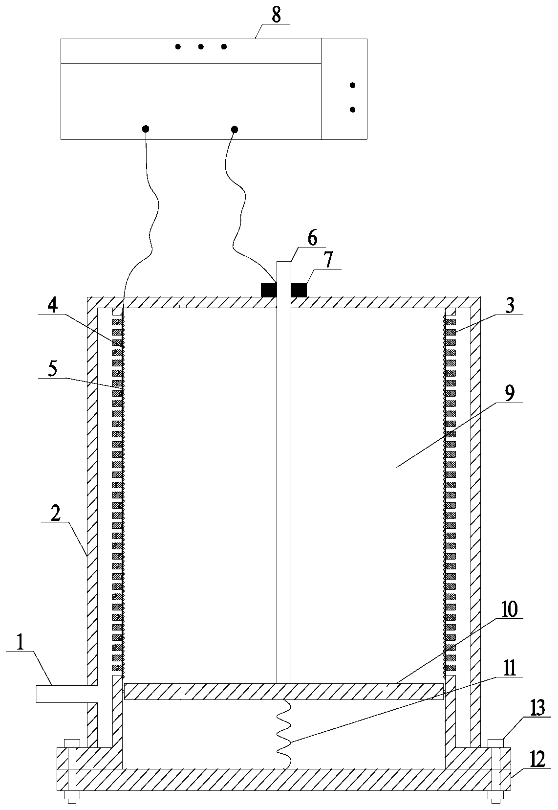
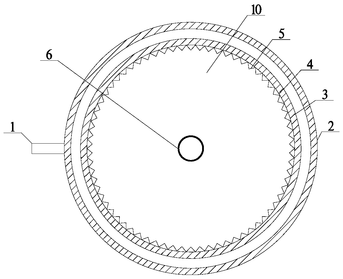
[0032] 8.6L of 001×7 styrene-based strongly acidic cation-exchange resin and 201×7 styrene-based strongly basic anion-exchange resin that were deactivated by NaCl, the mixing ratio of anion and cation resins is 2:1, using figure 1The shown membraneless ion exchange resin electrical regeneration device based on the cartridge electrode performs regeneration treatment. The main parameters of the device are as follows: shell height 20cm, inner diameter 35cm, support layer inner diameter 30cm, filter cloth aperture 0.05mm, mesh cathode aperture 0.5mm, filter anode aperture 50μm, resin layer height 10cm. The regeneration operating conditions are as follows: regeneration voltage 190V, regeneration current 4.0A ~ 8.0A, pure water flow rate 600.0L / h, regeneration time 2.0h. The resin regeneration effect is as follows: the exchange capacity of the cation exchange resin is 3.5 (dry) mmol / g, and the exchange capacity of the anion exchange resin is 2.0 (dry) mmol / g, both of which reach the...


PUM

PropertyMeasurementUnit
Apertureaaaaaaaaaa
The inside diameter ofaaaaaaaaaa

Abstract

The invention provides a membrane-free ion exchange resin electric regeneration device based on a filter element electrode. The membrane-free ion exchange resin electric regeneration device comprisesa cylindrical shell; a supporting layer, which is arranged on the inner side of the shell and is integrated with the shell through casting; filter cloth; a net-shaped cathode, wherein the filter clothand the net-shaped cathode are tightly attached to the inner side of the supporting layer in sequence; and a filter element anode, which extends into the shell from a cover plate above the shell along the central axis direction of the shell. The filter element anode is fixedly connected to a bottom plate above the shell through a fixing flange; an ion exchange resin bed layer is tightly filled inthe shell; the filter element anode is connected with the anode of a DC power supply, and the net-shaped cathode is connected with the cathode of the DC power supply. The device is simple in structure and easy to operate, and meanwhile, the problem of hydraulic bias caused by structural difference of multiple groups of filter element electrodes is avoided.

Description


Claims


Application Information

Patent Timeline
03 Jul 2020
Publication
CN111359680A