
Heat-shrinkable wrapping tape cutting device

A cutting device and winding tape technology, which is applied in metal processing and other directions, can solve the problems that heat-shrinkable winding tape cannot be adapted to the application, time-consuming manual cutting, and width errors, etc., and achieve the effect of simple structure, low cost, and improved cutting efficiency

Active Publication Date: 2020-07-03
CHANGCHUN INST OF OPTICS FINE MECHANICS & PHYSICS CHINESE ACAD OF SCI
View PDF8 Cites 0 Cited by
  • Summary
  • Abstract
  • Description
  • Claims
  • Application Information

AI Technical Summary

Problems solved by technology

The heat-shrinkable wrapping tape purchased has a standard width, such as 25mm, 50mm, 100mm, 150mm, 200mm, etc., but different types of cable connectors have different widths, so that the heat-shrinkable wrapping tape of the standard width cannot be adapted to the application. cut it manually
In actual operation, people usually use scissors to cut the heat-shrinkable wrapping tape to the width that matches the corresponding cable connector, but there are problems such as manual cutting is time-consuming, the width is wrong, and waste may be generated.

Method used


Image

  • Heat-shrinkable wrapping tape cutting device
  • Heat-shrinkable wrapping tape cutting device
  • Heat-shrinkable wrapping tape cutting device

Examples


Embodiment

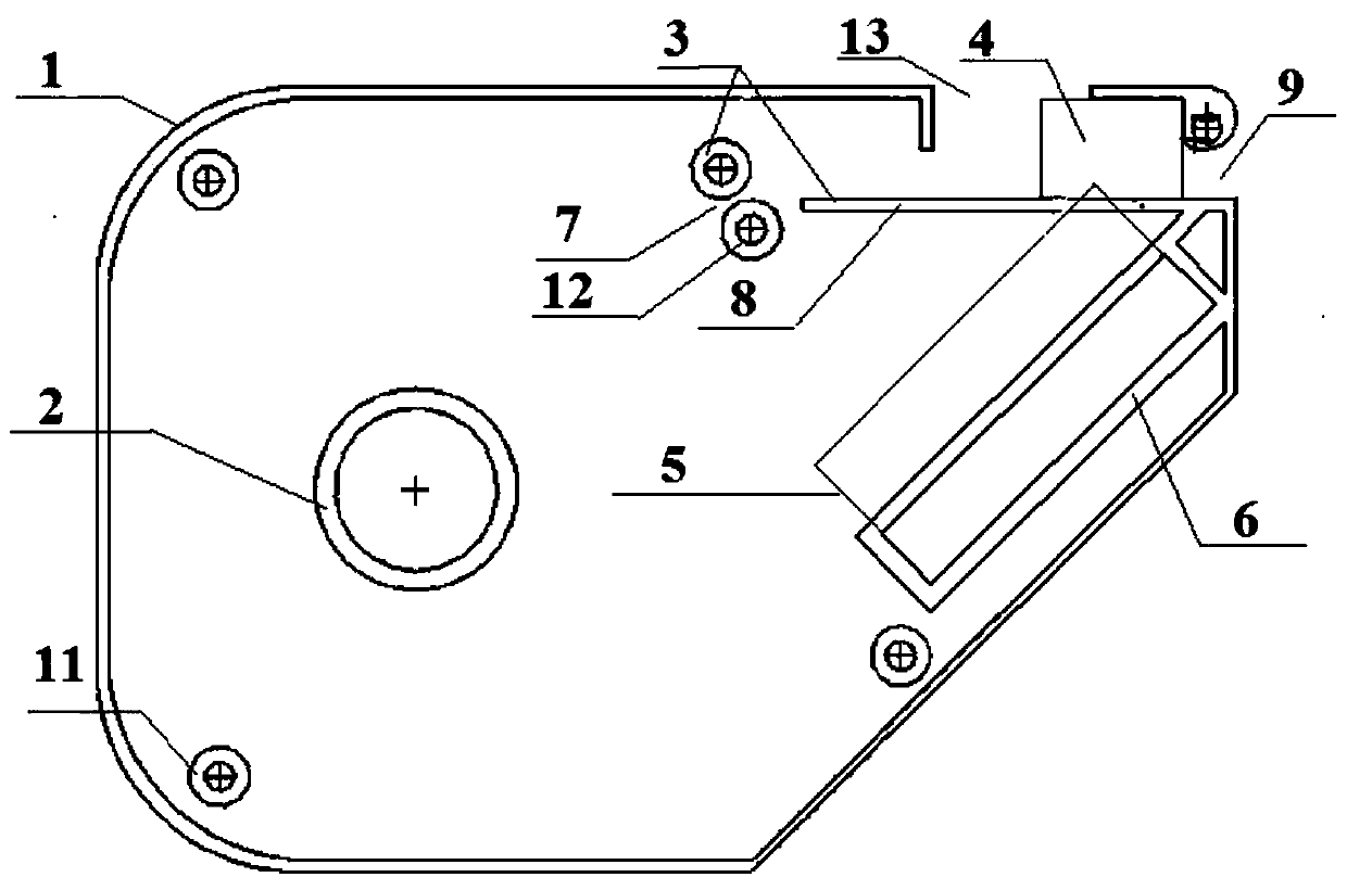
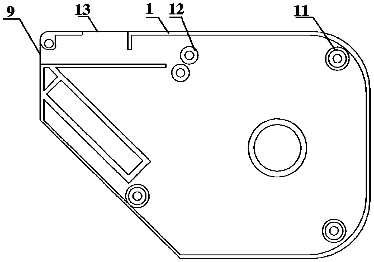
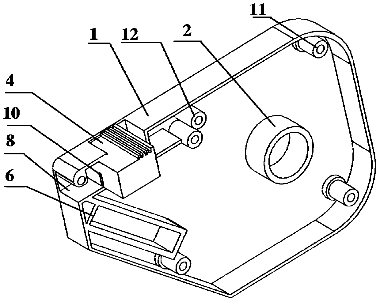
[0035] Such as Figure 1 to Figure 4 As shown, a heat-shrinkable winding tape cutting device includes a housing 1, the housing 1 is detachable, and the inner wall of the housing 1 is provided with a fixing part 2, a supporting part 3, a pressing part 4 and a blade 5; 2. It is used to fix the whole roll of heat-shrinkable wrapping tape. The support part 3 is used to support the output of the heat-shrinkable wrapping tape. The support part 3 includes a support shaft 7 and a support plate 8. The support plate 8 is connected to the tape outlet 9. The pressing part 4 is set relative to the support plate 8 and is used to compress the heat-shrinkable wrapping tape located on the support plate 8, the blade 5 is installed on the pressing part 4 and the extending direction of the blade 5 is consistent with the strip-out direction of the heat-shrinkable wrapping tape , and contact with the heat-shrinkable wrapping tape on the support plate 8 when the pressing part 4 presses the heat-shri...


PUM


Abstract

The invention discloses a heat-shrinkable wrapping tape cutting device. The heat-shrinkable wrapping tape cutting device comprises a shell which can be separated; a fixing part, a supporting part, a tight-pressing part and a blade are arranged on an inner wall of the shell; the fixing part is used for fixing the whole heat-shrinkable wrapping tape; the supporting part is used for supporting the outlet tape of the heat-shrinkable wrapping tape and comprises a supporting shaft and a supporting plate; the supporting plate is connected with a tape outlet; the tight-pressing part is arranged opposite to the supporting plate and is used for tightly pressing the heat-shrinkable wrapping tape positioned on the supporting plate; the blade is arranged on the tight-pressing part; an extending direction of a cutting edge of the blade is consistent with a tape outlet direction of the heat-shrinkable wrapping tape; and the heat-shrinkable wrapping tape is divided along a width direction of the heat-shrinkable wrapping tape. The heat-shrinkable wrapping tape can be cut into the regulated width according to different actual requirements, so that the problems in the prior art that manual cutting is time-consuming and it is possible to generate waste materials due to width error and the like are solved, and the cutting efficiency is improved. In addition, the heat-shrinkable wrapping tape cutting device has a simple structure and has the advantages of low cost, simplicity, convenience and easy use.

Description

technical field [0001] The invention relates to a cutting device, in particular to a heat shrink wrapping tape cutting device. Background technique [0002] The heat-shrinkable winding tape is made of radiation cross-linked polyolefin base material and special sealing hot-melt adhesive. When the heat-shrinkable winding tape is heated and installed, the inner composite adhesive layer melts while the base material shrinks radially, tightly It forms a solid whole with the coated object, has excellent wear resistance, corrosion resistance, impact resistance and good anti-ultraviolet and light aging properties. [0003] During the manufacturing process of aerospace cables, the diameter of the cable connector's tail cap does not match the cable diameter, and heat shrinkable wrapping tape is required to wrap and fill the tail cap. The heat-shrinkable wrapping tape purchased has a standard width, such as 25mm, 50mm, 100mm, 150mm, 200mm, etc., but the width of the tail cover of diff...

Claims


Application Information

Patent Timeline
Patent Type & Authority Applications(China)
IPC IPC(8): B26D1/02B26D7/26B26D7/00B29C45/00
CPCB26D1/02B26D7/00B26D7/2614B29C45/00
Inventor 张兴亮王威田景玉
Owner CHANGCHUN INST OF OPTICS FINE MECHANICS & PHYSICS CHINESE ACAD OF SCI
Learn More