Optical system, camera shooting module and electronic equipment

An optical system, relational technology, used in the field of photography

Pending Publication Date: 2020-07-03
TIANJIN OFILM OPTO ELECTRONICS CO LTD
View PDF0 Cites 3 Cited by
  • Summary
  • Abstract
  • Description
  • Claims
  • Application Information

AI Technical Summary

Problems solved by technology

[0003] Based on this, it is necessary to provide an optical system, camera module and electronic equipment for the problem of how to improve the imaging quality.

Method used


Image

  • Optical system, camera shooting module and electronic equipment
  • Optical system, camera shooting module and electronic equipment
  • Optical system, camera shooting module and electronic equipment

Examples


no. 1 example

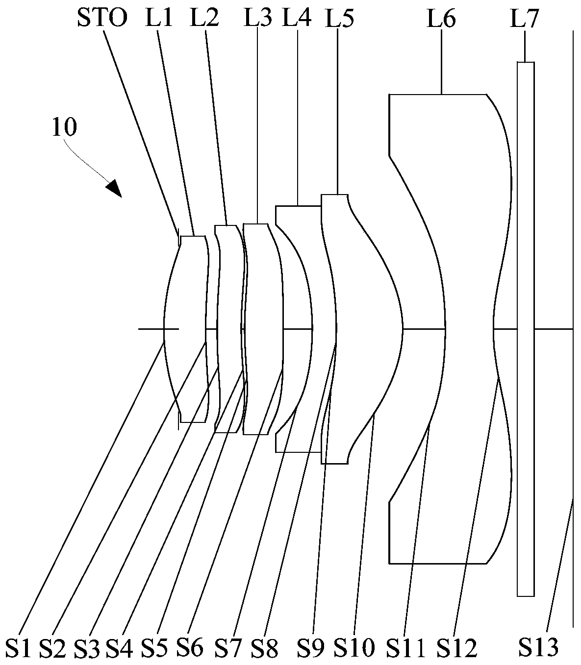
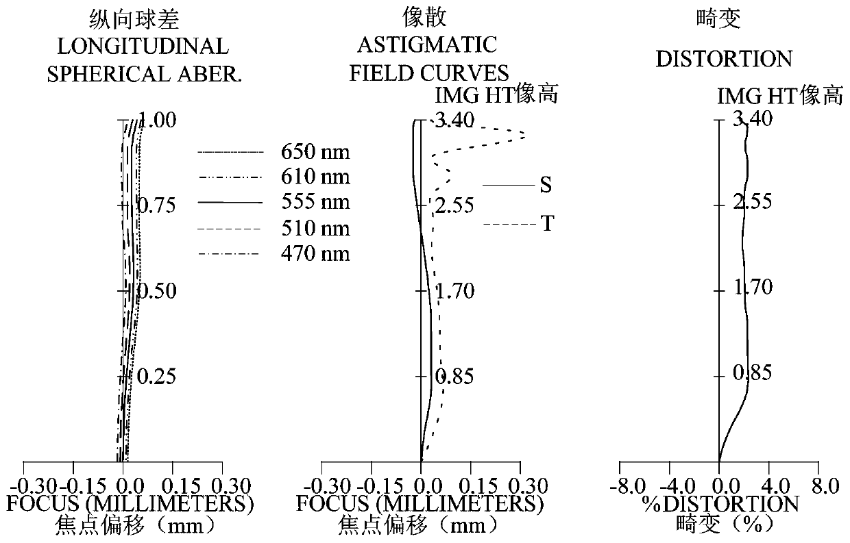
[0087] refer to figure 1 , in the first embodiment, the optical system 10 sequentially includes a stop STO, a first lens L1 with positive refractive power, a second lens L2 with negative refractive power, and a third lens L2 with positive refractive power from the object side to the image side. Lens L3, fourth lens L4 with negative refractive power, fifth lens L5 with positive refractive power, and sixth lens L6 with negative refractive power. figure 2 The longitudinal spherical aberration diagram, astigmatism diagram and distortion diagram of the optical system 10 in the first embodiment are included. The reference wavelengths of the systems in the following embodiments (the first embodiment to the fifth embodiment) are all 555 nm.

[0088] The object side S1 of the first lens L1 is convex at the paraxial position, and the image side S2 is concave at the paraxial position; the object side S1 is convex at the circumference, and the image side S2 is convex at the circumferenc...

no. 2 example

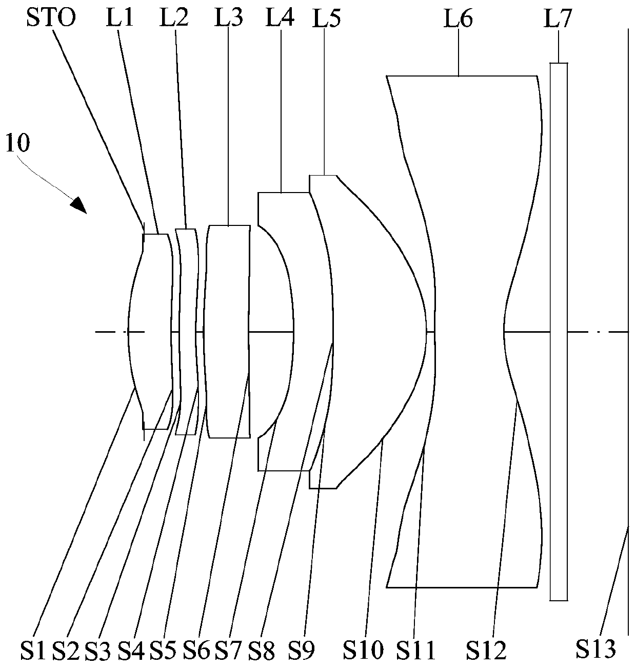
[0118] refer to image 3 , in the second embodiment, the optical system 10 sequentially includes a stop STO, a first lens L1 with positive refractive power, a second lens L2 with negative refractive power, and a third lens L2 with positive refractive power from the object side to the image side. Lens L3, fourth lens L4 with negative refractive power, fifth lens L5 with positive refractive power, and sixth lens L6 with negative refractive power. Figure 4 The longitudinal spherical aberration diagram, astigmatism diagram and distortion diagram of the optical system 10 in the second embodiment are included.

[0119] The object side S1 of the first lens L1 is convex at the paraxial position, and the image side S2 is concave at the paraxial position; the object side S1 is convex at the circumference, and the image side S2 is convex at the circumference.

[0120] The object side S3 of the second lens L2 is convex at the paraxial position, and the image side S4 is concave at the pa...

no. 3 example

[0135] refer to Figure 5 , in the third embodiment, the optical system 10 includes an aperture STO, a first lens L1 with positive refractive power, a second lens L2 with negative refractive power, and a third lens L2 with positive refractive power from the object side to the image side. Lens L3, fourth lens L4 with negative refractive power, fifth lens L5 with positive refractive power, and sixth lens L6 with negative refractive power. Figure 6 The longitudinal spherical aberration diagram, astigmatism diagram and distortion diagram of the optical system 10 in the third embodiment are included.

[0136] The object side S1 of the first lens L1 is convex at the paraxial position, and the image side S2 is concave at the paraxial position; the object side S1 is convex at the circumference, and the image side S2 is concave at the circumference.

[0137] The object side S3 of the second lens L2 is convex at the paraxial position, and the image side S4 is concave at the paraxial p...


PUM

PropertyMeasurementUnit
Effective focal lengthaaaaaaaaaa
F-numberaaaaaaaaaa

Abstract

The invention relates to an optical system, a camera shooting module and electronic equipment. The optical system includes a first lens with positive refractive power, a second lens with negative refractive power, a third lens with positive refractive power, a fourth lens, a fifth lens and a sixth lens with negative refractive power in sequence an object side to an image side, wherein an object-side surface of the first lens is a convex surface at the paraxial part, and an image-side surface is a concave surface at the paraxial part; and the fifth lens and the fourth lens form a lens group with positive refractive power. The optical system satisfies the following condition: Sag S10 / CT5 is greater than -1.1 and less than -0.5, wherein Sag S10 is the maximum vector height of the image side surface of the fifth lens, and CT5 is the thickness of the fifth lens on the optical axis. When the optical system meets the lens configuration and relational expression conditions, the center thickness of the fifth lens can be reasonably matched with the bending degree of the image side surface of the fifth lens, so that the fifth lens can well correct the system aberration, and the imaging quality of the optical system is facilitated to be improved.

Description

technical field [0001] The invention relates to the field of photography, in particular to an optical system, a photography module and electronic equipment. Background technique [0002] Since the application of camera lenses to electronic devices such as smart phones and tablet computers, the performance of camera lenses has undergone tremendous changes as users' demand for high-quality cameras has increased. Among them, the continuous improvement of the shooting effect of the camera lens has also become one of the focuses of people's expectations for technological progress. Especially with the popularization of electronic devices with camera functions in daily life, whether the image quality is good or not has become one of the key factors for people to choose electronic products. Contents of the invention [0003] Based on this, it is necessary to provide an optical system, a camera module and electronic equipment for the problem of how to improve the imaging quality. ...

Claims


Application Information

Patent Timeline
IPC IPC(8): G02B13/00G02B13/18
CPCG02B13/0045G02B13/006G02B13/18
Inventor 蔡雄宇兰宾利周芮
Owner TIANJIN OFILM OPTO ELECTRONICS CO LTD
Why Eureka
Try Eureka