Determination of Q factor in wireless charging system having complex resonant circuit

A wireless charger, resonant circuit technology, applied in circuit devices, battery data exchange, battery circuit devices, etc., can solve problems such as difficulty in determining the Q factor

Pending Publication Date: 2020-07-03
NXP USA INC
View PDF0 Cites 0 Cited by
  • Summary
  • Abstract
  • Description
  • Claims
  • Application Information

AI Technical Summary

Problems solved by technology

More complex resonant tanks result in multiple poles in

Method used


Image

  • Determination of Q factor in wireless charging system having complex resonant circuit
  • Determination of Q factor in wireless charging system having complex resonant circuit
  • Determination of Q factor in wireless charging system having complex resonant circuit

Examples


Embodiment Construction

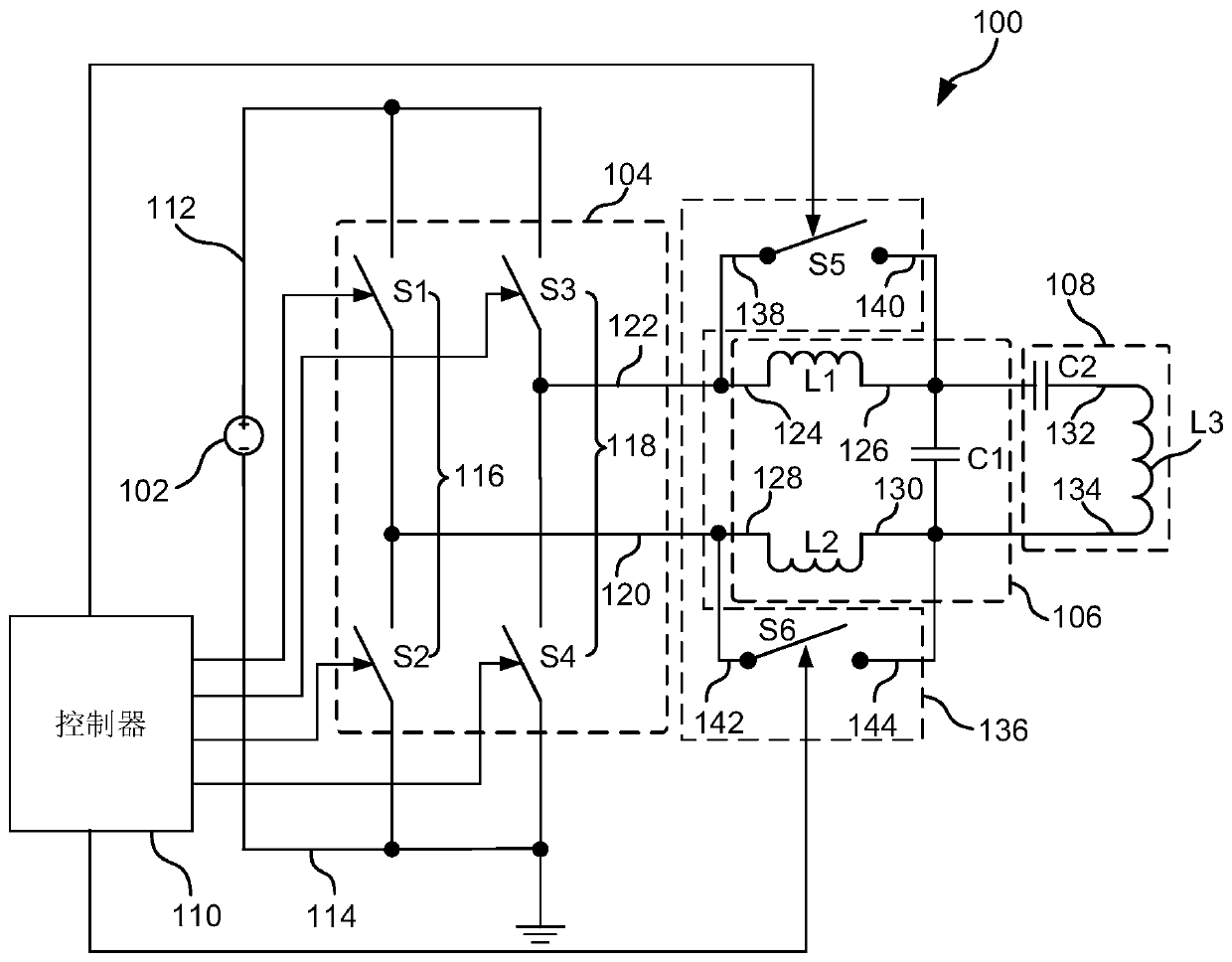
[0044] figure 1 is a schematic circuit diagram of a wireless charger 100 according to an exemplary embodiment of the present invention. The wireless charger 100 includes a power supply 102 , a rectifier 104 , a filter 106 , a resonant tank 108 , and a controller 110 .

[0045] The power supply 102 generates a driving signal 112 , and the driving signal 112 is used to drive the resonant tank 108 . The rectifier 104 rectifies the drive signal 112 and generates a rectified signal. In this preferred embodiment, the power supply 102 provides a DC voltage, and the rectifier 104 converts the DC voltage signal into an AC signal, and provides the AC signal to the resonant tank 108 .

[0046]In this preferred embodiment, the rectifier 104 is a full bridge rectifier circuit, which includes a first branch 116 and a second branch 118 . The first and second branches 116 , 118 are connected in parallel between the output 112 of the power supply 102 and ground 114 . Specifically, the firs...


PUM


Abstract

The invention relates to a wireless charger, which comprises a rectifier, a first filter including an inductor, a resonant circuit, and a second filter including a switch, wherein the rectifier receives a drive signal from a power supply and generates a rectified signal, the rectified signal is filtered by the first filter, the filtered signal is provided to the resonant circuit, the resonant circuit resonates to wirelessly provide electrical energy to a receiver, the switch of the second filter is connected in parallel with the inductor of the first filter, and in a detection phase in which the wireless charger determines the power factor of the resonant circuit, the switch is closed to bypass the inductor.

Description

technical field [0001] The invention relates to a wireless charger and a method for detecting a quality factor (Quality Factor, Q factor) of the wireless charger. In particular, the present invention relates to a wireless charger with a complex resonant tank, and a method for detecting the Q factor of the wireless charger with a complex resonant tank. Background technique [0002] In a wireless charger, the quality factor (Q-factor) is used to determine whether there is an unfavorable foreign object (eg, a metal object) within its charging area, which may be damaged by the charger by heating the metal. Typically, the Q factor is defined as the pole in the frequency range of interest. A signal with a swept frequency is applied to the resonant tank of the charger to determine the Q factor as V within that swept frequency band resonant / V drive The maximum ratio, where V resonant is the signal voltage on the transmitting coil, V drive is the signal voltage applied to the r...

Claims


Application Information

Patent Timeline
IPC IPC(8): H02J50/00H02J7/00
CPCH02J50/00G01R27/2688H02J50/12H02J50/60Y02B70/10H02M7/4815H02J7/00034H02M7/44
Inventor 江登宇王德昌王力毛欢
Owner NXP USA INC
Why Eureka
Try Eureka