
Supporting equipment for bridge construction in the field of bridge engineering

A technology of bridge construction and bridge engineering, applied in bridge construction, bridges, mechanical equipment, etc., can solve the problems of easy movement of mechanical equipment and inconvenient fixing of mechanical equipment, and achieve the effect of increasing stability

Active Publication Date: 2021-12-07
NANJING CHINA CONSTR CHEM EQUIP MFG
View PDF7 Cites 0 Cited by
  • Summary
  • Abstract
  • Description
  • Claims
  • Application Information

AI Technical Summary

Problems solved by technology

[0004] The purpose of the present invention is to solve the shortcomings in the prior art that the support equipment is not convenient to fix the mechanical equipment during use, resulting in the shortcomings of easy movement of the mechanical equipment, and proposes a bridge construction support equipment in the field of bridge engineering

Method used


Image

  • Supporting equipment for bridge construction in the field of bridge engineering
  • Supporting equipment for bridge construction in the field of bridge engineering
  • Supporting equipment for bridge construction in the field of bridge engineering

Examples


Embodiment 1

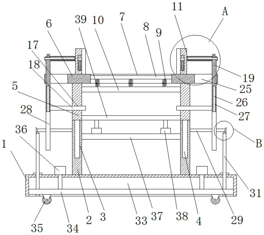
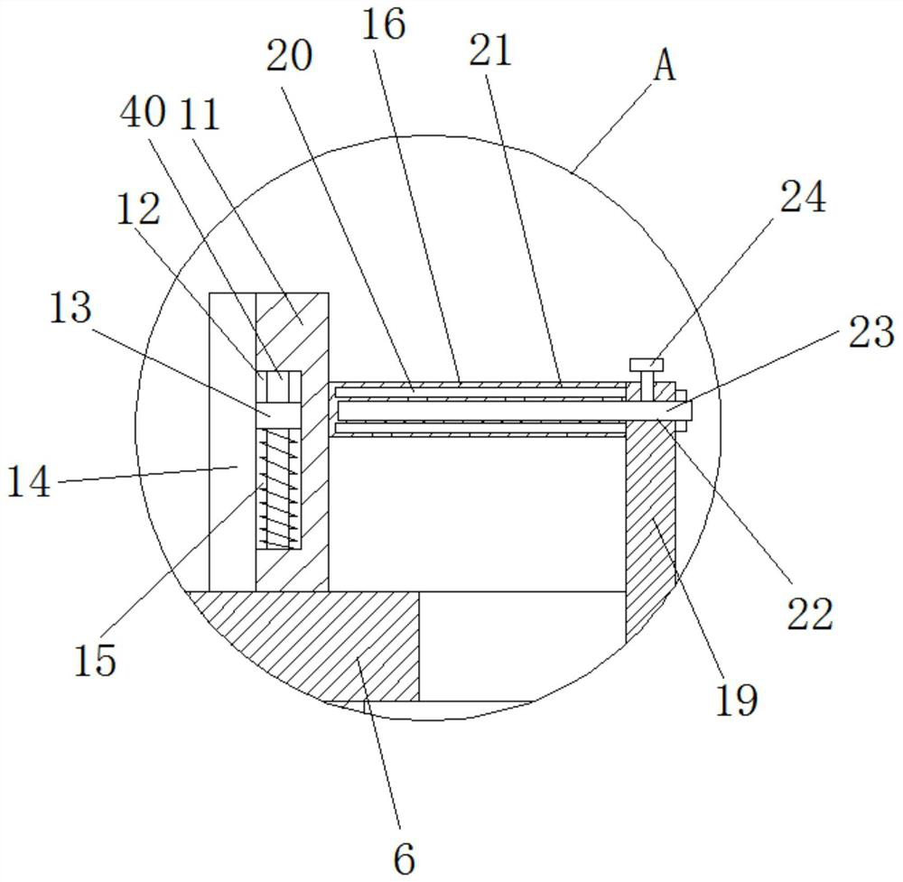
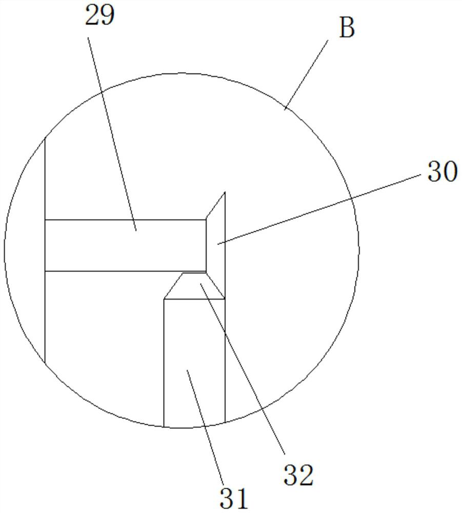
[0030] refer to Figure 1-5 , a support device for bridge construction in the field of bridge engineering, comprising a mobile seat 1, two first fixed plates 2 are fixedly installed on the top of the mobile seat 1, and second fixed plates 2 are slidably installed on the tops of the two first fixed plates 2 plate 5, the top of the two second fixed plates 5 is fixedly installed with the same installation top plate 6, and the top of the installation top plate 6 is slidably installed with two slide plates 11, and the sides of the two slide plates 11 close to each other are all slidably installed with splints 14, The installation top plate 6 is provided with a placement hole 7, and a placement plate 8 is slidably installed in the placement hole 7. Two slide holes 25 are provided on the installation top plate 6, and vertical plates 19 are slidingly installed in the two slide holes 25. The sides of the boards 19 that are close to each other are slidingly installed with connecting pla...

Embodiment 2

[0041] refer to Figure 1-5 , a supporting device for bridge construction in the field of bridge engineering, comprising a mobile seat 1, two first fixed plates 2 are installed on the top of the mobile seat 1 through bolts, and the tops of the two first fixed plates 2 are slidingly installed with the second Two fixed plates 5, the tops of the two second fixed plates 5 are fixed with the same installation top plate 6 by bolts, the top of the installation top plate 6 is slidably installed with two slide plates 11, and the sides of the two slide plates 11 that are close to each other are all slidably installed There is a splint 14, a placement hole 7 is provided on the installation top board 6, a placement board 8 is slidably installed in the placement hole 7, two sliding holes 25 are provided on the installation top board 6, and vertical plates 19 are slidingly installed in the two sliding holes 25 , the sides of the two vertical plates 19 that are close to each other are slidab...


PUM


Abstract

The present invention belongs to the field of bridge engineering, in particular to a supporting device for bridge construction in the field of bridge engineering. Aiming at the problem that the existing supporting device is inconvenient to fix the mechanical equipment during use, resulting in the easy movement of the mechanical equipment, the following proposal is now proposed , which includes a moving seat, the top of the moving seat is fixedly installed with two first fixed plates, the tops of the two first fixed plates are all slidably installed with a second fixed plate, and the tops of the two second fixed plates are fixedly installed with For the same installation top plate, two slide plates are slidably installed on the top of the installation top plate, and splints are slidably installed on the sides where the two slide plates are close to each other. The stability of the equipment during use can be adapted to equipment of different sizes by adjusting the distance between the two splints, and the equipment can be shock-absorbed and height-adjusted.

Description

technical field [0001] The invention relates to the technical field of bridge engineering, in particular to a supporting device for bridge construction in the field of bridge engineering. Background technique [0002] Bridge construction refers to the process of building a bridge according to the design content; it mainly refers to bridge construction technology, construction organization, construction management, construction quality, etc. Bridge construction requires more mechanical equipment, and mechanical equipment needs to be supported when in use . [0003] The existing supporting equipment is inconvenient to fix the mechanical equipment during use, which leads to the easy movement of the mechanical equipment. Therefore, we propose a supporting equipment for bridge construction in the field of bridge engineering to solve the above problems. Contents of the invention [0004] The purpose of the present invention is to solve the disadvantages in the prior art that th...

Claims


Application Information

Patent Timeline
Patent Type & Authority Patents(China)
IPC IPC(8): F16M11/42F16M11/26F16M11/04F16F15/067E01D21/00
CPCE01D21/00F16F15/067F16M11/04F16M11/26F16M11/42F16M2200/08
Inventor 王斌
Owner NANJING CHINA CONSTR CHEM EQUIP MFG
Learn More