
Roller input device

A technology of input devices and rollers, applied in the input/output process of data processing, instruments, electrical digital data processing, etc., can solve problems such as unsatisfactory usage conditions

Active Publication Date: 2020-07-07
CHICONY ELECTRONICS
View PDF6 Cites 1 Cited by
  • Summary
  • Abstract
  • Description
  • Claims
  • Application Information

AI Technical Summary

Problems solved by technology

However, this type of segmented scroll wheel input device still cannot meet certain usage conditions (for example, the scroll wheel needs to be scrolled for a long time or a long distance, or a finer scrolling operation is required)

Method used


Image

  • Roller input device
  • Roller input device
  • Roller input device

Examples


Embodiment Construction

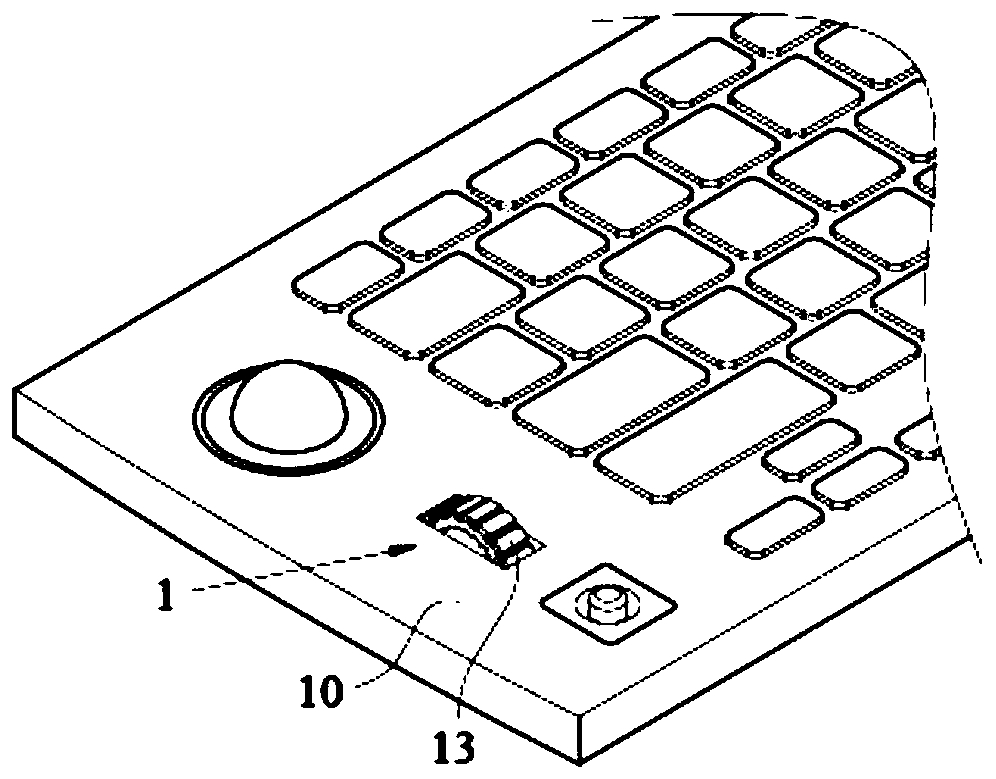
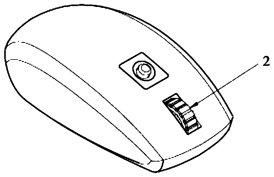
[0070] figure 1 It is an application schematic diagram of an embodiment of the roller input device of the present invention, figure 2 It is an application schematic diagram of another embodiment of the roller input device of the present invention. Such as figure 1 As shown, the wheel input device 1 of the embodiment of the present invention is an input device for a computer, and is used to manipulate the computer page to perform actions (such as dragging, scrolling pages up and down, or switching menus, etc.). In this embodiment, the wheel input device 1 is integrated with a computer keyboard. In another embodiment, such as figure 2 As shown, the wheel input device 2 can also be applied to a computer mouse, which is not limited.

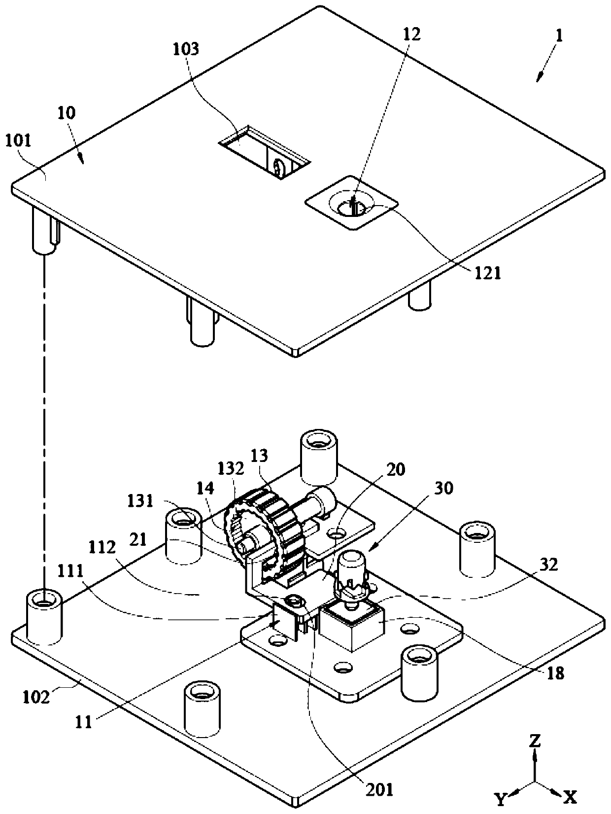
[0071] Such as figure 1 , image 3 and Figure 4 shown, where image 3 It is an exploded perspective view of the first embodiment of the roller input device of the present invention, Figure 4It is another exploded perspective view of the ...


PUM


Abstract

The invention discloses a roller input device. The roller input device comprises a shell, a driven part and a driving part; the roller is arranged in the shell in a pivoted mode and comprises an annular tooth part; the driven part is movably arranged in the shell and comprises an abutting part and a first magnetic module; the driving part comprises a second magnetic module; the driving part is arranged in the shell and can operably move in a first mode or a second mode; the first magnetic module and the second magnetic module attract each other or repel each other, so that the driven part is driven to move to a first position or a second position relative to the shell, and the abutting part and the annular tooth part abut against each other or are separated from each other.

Description

technical field [0001] The invention relates to an input device, in particular to a roller input device. Background technique [0002] Generally, a computer is equipped with a wheel input device. For example, a keyboard or a mouse may be provided with a wheel input device, so that actions such as dragging, scrolling pages up and down, or switching menus can be performed through the wheel input device. [0003] The current common roller input device generally has a roller and an elastic top ball. The roller body is provided with a tooth surface. The elastic top ball includes a spring and a metal ball connected to the end of the spring. The elastic top ball pushes against the tooth surface on the roller body. Make the scroll wheel produce segmental tactile sensation when it is rotated by operation, for example, every time the scroll wheel rotates a scale, the operator will feel the tactile sensation of pause, and the screen page is scrolled for a predetermined distance. Howev...

Claims


Application Information

Patent Timeline
Patent Type & Authority Applications(China)
IPC IPC(8): G06F3/0362G06F3/0354
CPCG06F3/0362G06F3/03543
Inventor 李育龙
Owner CHICONY ELECTRONICS
Learn More