Display panel and display device

A technology of display panel and display area, which is applied in identification devices, nonlinear optics, instruments, etc., can solve the problems of unfavorable narrow-frame full-screen design of display panel, occupying non-display area of ​​display panel screen, etc.

Active Publication Date: 2020-07-07
SHANGHAI AVIC OPTOELECTRONICS
View PDF8 Cites 39 Cited by
  • Summary
  • Abstract
  • Description
  • Claims
  • Application Information

AI Technical Summary

Problems solved by technology

[0003] Driver chip binding on glass (COG, Chip On Glass) is a technology used more in current display modules, but this kind of direct binding of driver chip (integrated circuit, IC) on t...

Method used


Image

  • Display panel and display device
  • Display panel and display device
  • Display panel and display device

Examples


Embodiment Construction

[0033] The technical solutions in the embodiments of the present invention will be clearly and completely described below in conjunction with the accompanying drawings in the embodiments of the present invention. Obviously, the described embodiments are only some of the embodiments of the present invention, not all of them. Based on the embodiments of the present invention, all other embodiments obtained by those skilled in the art without making creative efforts belong to the protection scope of the present invention.

[0034] It should be noted that, in the case of no conflict, the embodiments in the present application and the features in the embodiments can be combined with each other. The present application will be described in detail below with reference to the accompanying drawings and embodiments.

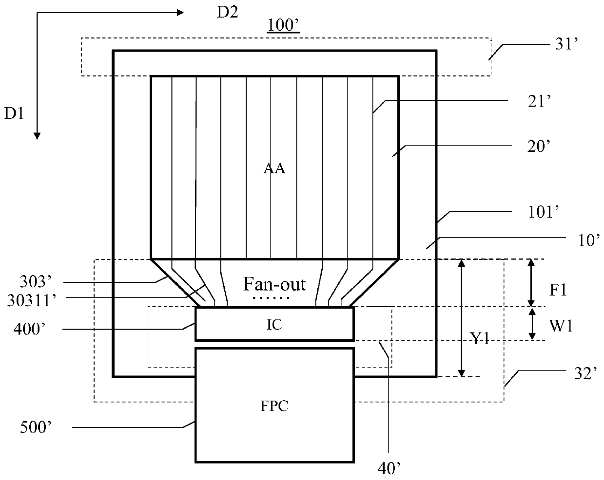
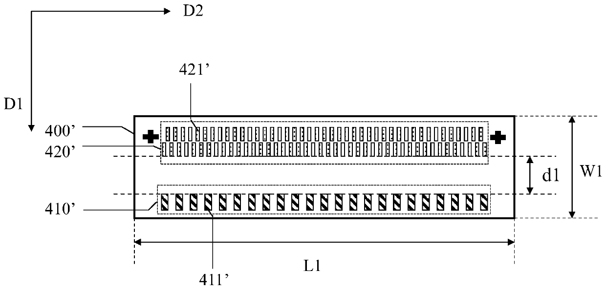
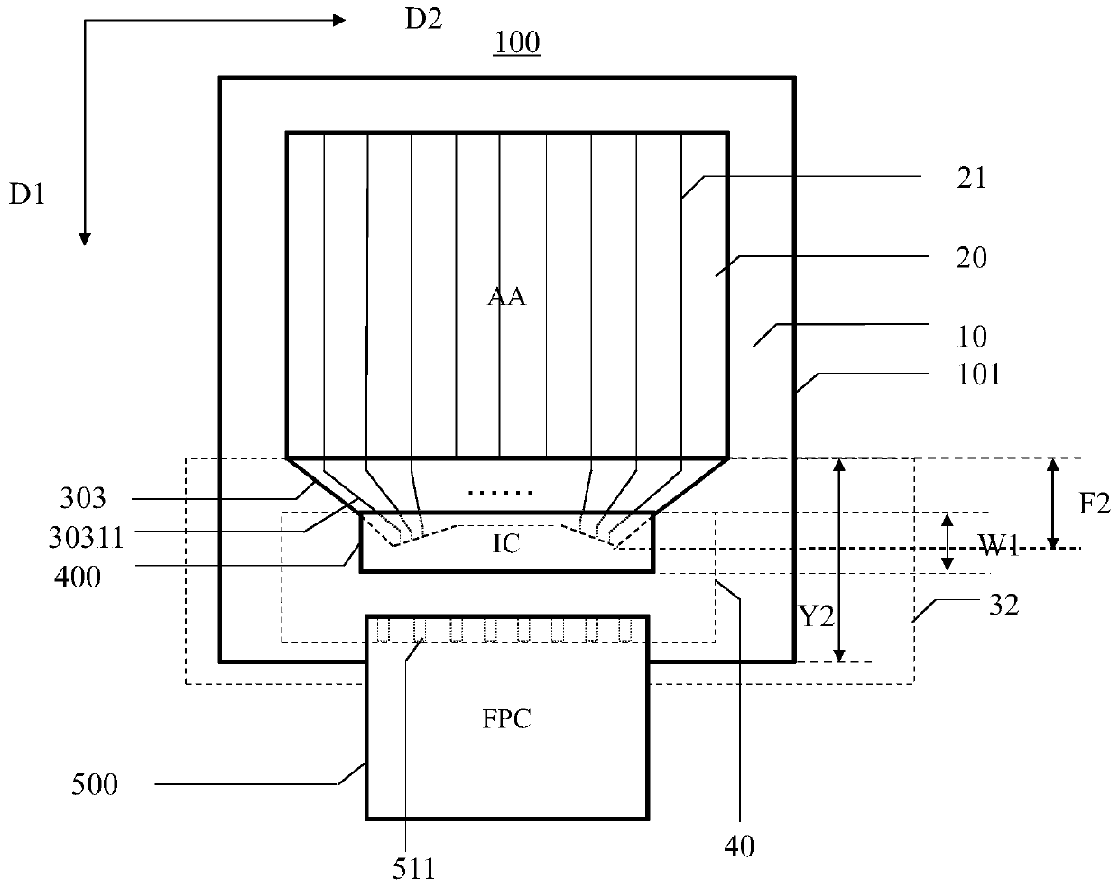
[0035] figure 1 It is a schematic plan view of a display panel provided by the prior art, figure 2 It is a schematic plan view of a drive chip in a display panel provid...


PUM


Abstract

The invention discloses a display panel and a display device. The display panel comprises a binding area and a fan-out area, wherein the binding area is used for binding a driving chip, and the fan-out area comprises a plurality of fan-out leads; a plurality of binding pads in the binding area comprise a first pad column and a second pad column; the first pad column is positioned on one side, close to the display area, of the second pad column; the first pad column comprise a plurality of first pads; the plurality of first pads are arranged in at least two columns; the first pad column comprises at least one inclined section; and the inclined section comprises at least three first pads which are obliquely arranged towards one side far away from the display area and are arranged in sequence. With such an arrangement mode adopted, an area for arranging the fan-out leads can be increased by the amount of the displacement of at least some fan-out leads to the binding area, and therefore, the fan-out area and the binding area are overlapped in a first direction, the overall height of the fan-out area and the binding area of the driving chip in the first direction is reduced, the lower frame of the display panel is shrunk, and a higher screen-to-body ratio is achieved.

Description

technical field [0001] The present application relates to the field of display technology, in particular to a display panel and a display device. Background technique [0002] With the continuous development of the display market, consumers have increasingly stringent requirements on the visual effect of the display screen, not only have diversified requirements on the appearance design of the display screen, but also have higher and higher requirements on the screen ratio. The resulting trend of full-screen technology is to pursue a screen-to-body ratio greater than or equal to 90% through an ultra-narrow bezel or even bezel-less design. With the total area of ​​the body unchanged, the display area is maximized and the visual effect is more vivid. stunning. [0003] Driver chip binding on glass (COG, Chip On Glass) is a technology used more in current display modules, but this kind of direct binding of driver chip (integrated circuit, IC) on the display panel glass will oc...

Claims


Application Information

Patent Timeline
IPC IPC(8): G09F9/35G02F1/1345
CPCG09F9/35G02F1/1345G02F1/13458G02F1/13452G02F1/13454G02F1/136286G02F1/1368
Inventor 简守甫秦锋秦丹丹钟本顺
Owner SHANGHAI AVIC OPTOELECTRONICS
Why Eureka
Try Eureka