A center of gravity lifting crane anti-sway device

An anti-sway device and lifting technology, which is applied to cranes, trolley cranes, transportation and packaging, etc., can solve problems such as heavy objects are easy to shake

Active Publication Date: 2021-09-21
山东国新起重机械有限公司
View PDF0 Cites 0 Cited by
  • Summary
  • Abstract
  • Description
  • Claims
  • Application Information

AI Technical Summary

Problems solved by technology

[0005] The object of the present invention is to solve the problem that the above-mentioned heavy objects are easy to shake during the hoisting process, and to provide a center-of-gravity lifting type crane anti-sway device that reduces the shaking amplitude of the heavy objects

Method used


Image

  • A center of gravity lifting crane anti-sway device
  • A center of gravity lifting crane anti-sway device
  • A center of gravity lifting crane anti-sway device

Examples


Embodiment 1

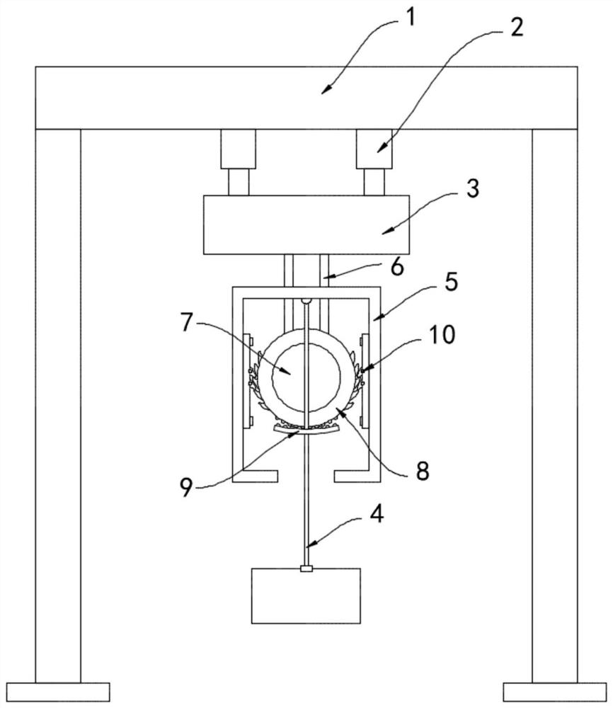
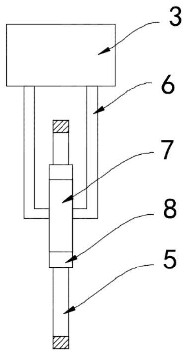
[0019] Such as Figure 1-2 As shown, a center of gravity lifting type crane anti-sway device includes a support frame 1, a lifting mechanism 2, a running trolley 3 and a sling 4, an anti-sway frame 5 is provided under the running trolley 3, and the upper end of the sling 4 is connected to the anti-sway The inner top surface of the rocking frame body 5 is fixedly connected, and the lower end of the running trolley 3 is fixedly connected with two L-shaped connecting rods 6, and a fixed wheel 7 is fixedly installed between the two L-shaped connecting rods 6, and the fixed wheel 7 is located at the In the rocking frame body 5 and parallel to the anti-rolling frame body 5, a rotating ring 8 is connected to the outer ring side wall of the fixed wheel disc 7, and balls are arranged between the fixed wheel disc 7 and the rotating ring 8, so that the sliding friction becomes Rolling friction reduces friction consumption and prolongs its service life. The lower end of the rotating ring ...

Embodiment 2

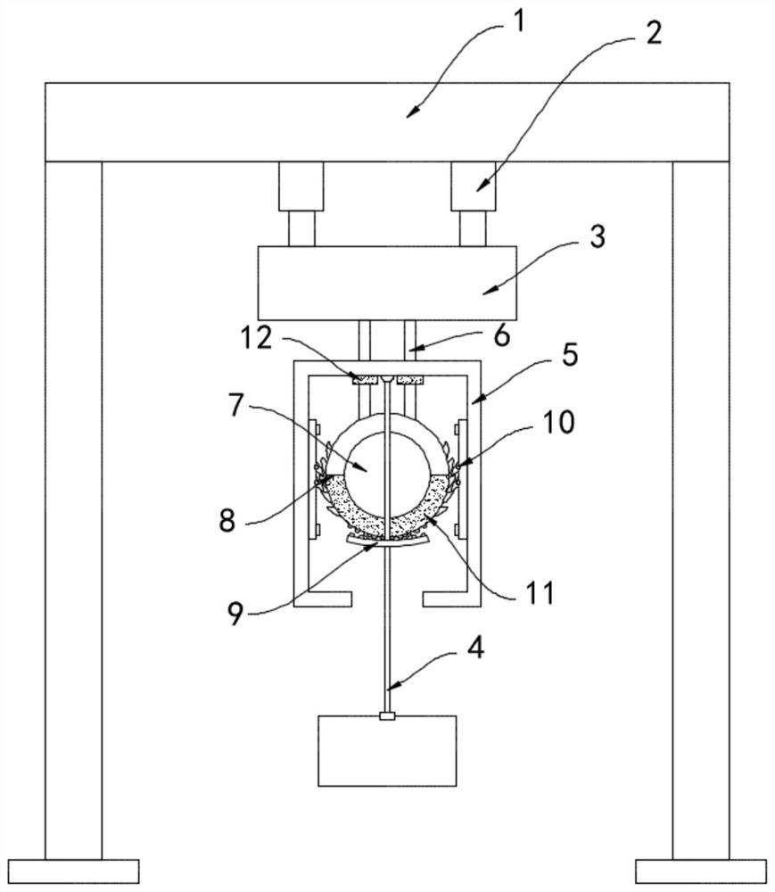
[0023] Such as image 3 As shown, the difference between this embodiment and Embodiment 1 is that the rotating ring 8 is composed of two semi-circular rings 11, the semi-circular ring 11 located below is made of magnetic material, and the inner top surface of the anti-rolling frame 5 A permanent magnet block 12 is fixedly installed, and the same polarity repels each other between the permanent magnet block 12 and the semi-circular ring 11 .

[0024] In this embodiment, when the sling 4 and the heavy object are not swinging, the permanent magnet block 12 is far away from the magnetic semi-circular ring 11, and when the heavy object drives the sling 4 to swing, it drives the rotating ring 8 to rotate, The magnetic semi-circular ring 11 located at the bottom rotates to a higher position and approaches the direction of the permanent magnet block 12, that is, when the sling 4 swings, it needs to overcome the repulsive force between the permanent magnetic block 12 and the semi-circu...


PUM


Abstract

The invention belongs to the field of crane accessories, and in particular relates to a center-of-gravity lifting type crane anti-sway device, which includes a support frame, a lifting mechanism, a running trolley and a sling. The upper end of the upper end is fixedly connected with the inner top surface of the anti-rolling frame, and the lower end of the running trolley is fixedly connected with two L-shaped connecting rods, and a fixed wheel is fixedly installed between the two L-shaped connecting rods. The roulette is located in the anti-rolling frame and is arranged parallel to the anti-rolling frame. A rotating ring is connected to the side wall of the outer ring of the fixed roulette. A rack is fixedly connected, and the rack engages with the lower end of the rotating ring, and ratchets are provided on both sides of the rotating ring. The invention can convert the kinetic energy and inertial potential energy of the weight swinging upwards due to inertia and wind force into gravitational potential energy, so that the swinging energy is quickly converted and consumed, and a good anti-rolling effect is achieved.

Description

technical field [0001] The invention belongs to the field of crane accessories, in particular to a center-of-gravity lifting type crane anti-sway device. Background technique [0002] A crane refers to a multi-action hoisting machine that lifts vertically and transports heavy objects horizontally within a certain range. The working characteristics of lifting equipment are intermittent movements, that is, the actions of taking, moving, and unloading in a working cycle. The corresponding mechanisms work alternately, and the development and use of cranes in the market are becoming more and more extensive. [0003] When the existing crane lifts heavy objects, the heavy objects will swing back and forth in the plumb plane due to the inertial force and horizontal wind load. If the heavy object swings too much, the suspension may not be firm, and there is a greater safety hazard. Hidden dangers; at the same time, the swinging heavy objects are not easy to land, and when the heavy ...

Claims


Application Information

Patent Timeline
Patent Type & Authority Patents(China)
IPC IPC(8): B66C13/06B66C19/00
CPCB66C13/06B66C19/00
Inventor 石金秀肖超
Owner 山东国新起重机械有限公司
Why Eureka
Try Eureka