Stainless steel supporting leg structure

A technology of supporting feet and stainless steel, applied in the direction of supporting the machine, machine/stand, engine frame, etc., can solve the problem that the staff cannot enter the machine for cleaning and inspection, the height of the supporting feet cannot be adjusted freely, and the height of the quick freezer cannot be increased. and other problems, to achieve the effect of increasing the installation range, simple and convenient operation, and compact structure

Active Publication Date: 2020-07-10
麦卡尼食品设备(中山)有限公司
View PDF7 Cites 1 Cited by
  • Summary
  • Abstract
  • Description
  • Claims
  • Application Information

AI Technical Summary

Problems solved by technology

[0002] In the existing life, if the quick-freezer is damaged during the working process, the staff needs to enter the bottom of the machine to check it. At the same time, most of the bottom of the quick-freezer has a support foot structure, but the bottom of the existing quick-freezer Most of the supporting feet cannot adjust their height freely, so that the height of the quick-freezing machine cannot be raised, and the staff cannot enter the bottom of the machine for cleaning and inspection. At the same time, the quick-freezing machine cannot be installed and used on the ground of different workshops today.

Method used


Image

  • Stainless steel supporting leg structure
  • Stainless steel supporting leg structure
  • Stainless steel supporting leg structure

Examples


Embodiment

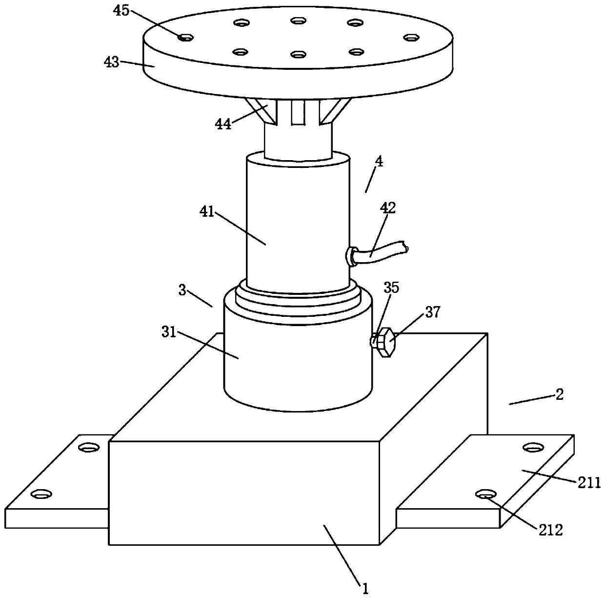
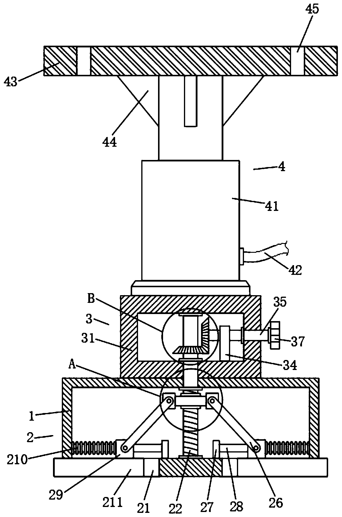
[0023] A stainless steel support foot structure, including a fixed box 1, a support mechanism 2, a transmission mechanism 3 and a telescopic mechanism 4, the inside of the fixed box 1 is provided with a support mechanism 2, the top of the fixed box 1 is provided with a transmission mechanism 3, and the transmission mechanism 3 The top is provided with telescopic mechanism 4.

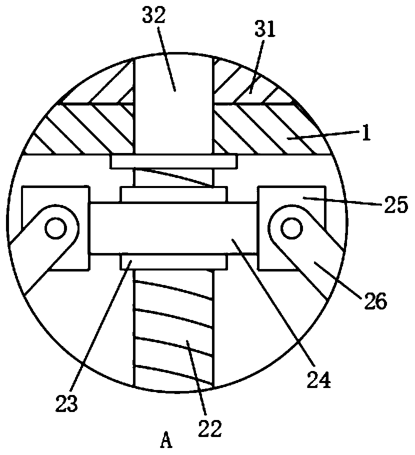
[0024] Wherein, the support mechanism 2 includes a chute 21, the two ends of the bottom of the fixed box 1 are dug with chute 21, the bottom and the top of the inner wall of the fixed box 1 are rotatably connected with a threaded rod 22, and the outer side of the threaded rod 22 is threaded with a second A slide block 23, the outer side of the first slide block 23 is fixedly connected with a fixed plate 24, the two ends of the fixed plate 24 are all fixedly connected with a connecting plate 25, and one side of the connecting plate 25 is connected with a connecting rod 26 in rotation, and the fixed box 1 ...


PUM


Abstract

The invention discloses a stainless steel supporting leg structure. The structure comprises a fixed box, a supporting mechanism, a driving mechanism and an extensible mechanism, and the supporting mechanism is arranged inside the fixed box. The structure is compact, the operation is easy and convenient, and the practicability is high. Via the arrangement of an electric extensible rod and a limiting plate, the height of the structure can be freely adjusted and changed and, in the meantime, reinforced rib plates are additionally installed on the outer side of a piston rod of the electric extensible rod and on the bottom of the limiting plate, so the installation of the structure is more stable. Furthermore, the driving mechanism and the supporting mechanism are arranged below the electric extensible rod to enable free extension of a supporting plate and in the meantime match with a fastener to better fix the structure on the ground, so the stability of the support of the structure to aninstant freezer is improved. Meanwhile, via the arrangement of the structure on the bottom of the instant freezer, the instant freezer can be installed and used on the ground of different existing workshops, so the installation range of the instant freezer is widened.

Description

technical field [0001] The invention belongs to the field of supporting foot structures, in particular to a stainless steel supporting foot structure. Background technique [0002] In the existing life, if the quick-freezer is damaged during the working process, the staff needs to enter the bottom of the machine to check it. At the same time, most of the bottom of the quick-freezer has a support foot structure, but the bottom of the existing quick-freezer Most of the supporting feet cannot adjust their height freely, so that the height of the quick-freezing machine cannot be raised, and the staff cannot enter the bottom of the machine for cleaning and inspection. At the same time, the quick-freezing machine cannot be suitable for installation and use on the ground of different workshops today. Contents of the invention [0003] The object of the present invention is to provide a stainless steel support leg structure in order to solve the above problems, which solves the pr...

Claims


Application Information

Patent Timeline
Patent Type & Authority Applications(China)
IPC IPC(8): F16M11/28F16M11/04F16M7/00
CPCF16M7/00F16M11/04F16M11/28
Inventor 杰弗里·陈
Owner 麦卡尼食品设备(中山)有限公司
Why Eureka
Try Eureka