Automatic monitoring equipment for distributed power distribution terminal

A power distribution terminal and automatic monitoring technology, which is applied in mechanical equipment, televisions, color televisions, etc., can solve the problems of increasing the danger of operators, lack of installation and debugging, and increasing the difficulty of installation, so as to increase convenience and ensure effectiveness And the effect of persistence and prolonging the service life

Inactive Publication Date: 2020-07-10
STATE GRID HEBEI ELECTRIC POWER CO LTD +1
View PDF8 Cites 2 Cited by
  • Summary
  • Abstract
  • Description
  • Claims
  • Application Information

AI Technical Summary

Problems solved by technology

[0003] During the on-site installation of monitoring equipment, the specific installation needs to be adjusted according to the site environment to achieve the best monitoring effect. The existing monitoring equipment does not have the function of installation and debugging during the installation process, so in During the installation process, the difficulty of installation is greatly increased, and it is very inconvenient to debug. For the debugging of high-altitude operations, long-term debugging increases the danger of operators, and at the same time, the installation efficiency is low. For this reason, we have designed a Distributed power distribution terminal automatic monitoring equipment to solve the above problems

Method used


Image

  • Automatic monitoring equipment for distributed power distribution terminal
  • Automatic monitoring equipment for distributed power distribution terminal
  • Automatic monitoring equipment for distributed power distribution terminal

Examples


Embodiment Construction

[0027] The technical solution of this patent will be further described in detail below in conjunction with specific embodiments.

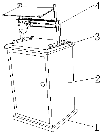
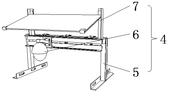
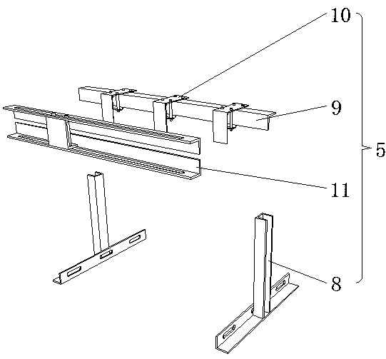
[0028] see Figure 1-7 , an automatic monitoring device for a distributed power distribution terminal, comprising a base 1, a box body 2 is fixedly connected to the top of the base 1, a cover plate 3 is fixedly connected to the top of the box body 2, and a monitoring component 4 is fixedly connected to the top of the cover plate 3 , the monitoring assembly 4 includes a mounting frame 5, the front of the mounting frame 5 is provided with a monitoring camera 6, the top of the mounting frame 5 is fixedly connected with a rain shelter 7, the mounting frame 5 includes two brackets 8, and the bracket 8 includes a fixed rod 12, fixed The outer side of the rod 12 is provided with three strip-shaped holes, and the three strip-shaped holes are equidistant and evenly distributed. The inner side of the fixed rod 12 is fixedly connected with a column 13 along t...


PUM


Abstract

The invention discloses automatic monitoring equipment for a distributed power distribution terminal. The automatic monitoring equipment includes a base, wherein the top of the base is fixedly connected with a box body; the top of the box body is fixedly connected with a cover plate; the top of the cover plate is fixedly connected with a monitoring assembly. The monitoring assembly comprises a mounting frame; a monitoring camera is arranged on the front surface of the mounting frame; the top of the mounting frame is fixedly connected with a rain shelter; the mounting frame comprises two brackets; a supporting rod is fixedly connected to the top between the two brackets; the supporting rod is fixedly connected with an adjusting mechanism through three connecting pieces. The adjusting mechanism comprises two limiting rods and a sliding block is slidably connected between the two limiting rods. The automatic monitoring equipment for the distributed power distribution terminal relates to the technical field of monitoring equipment, the monitoring assembly is arranged, and the monitoring camera is installed on the adjusting mechanism, so that the convenience of installation and debugging is greatly improved.

Description

technical field [0001] The invention relates to a power distribution terminal monitoring device, in particular to a distributed power distribution terminal automatic monitoring device. Background technique [0002] Power distribution terminals are widely used and distributed in a wide range. In some places, the situation is complicated. Therefore, it is necessary to install monitoring equipment in dangerous areas to monitor the surrounding environment. Unsafe conditions can be found in time and corrected in time to avoid external forces. The occurrence of sabotage accidents. [0003] During the on-site installation of monitoring equipment, the specific installation needs to be adjusted according to the site environment to achieve the best monitoring effect. The existing monitoring equipment does not have the function of installation and debugging during the installation process, so in During the installation process, the difficulty of installation is greatly increased, and ...

Claims


Application Information

Patent Timeline
Patent Type & Authority Applications(China)
IPC IPC(8): H04N5/225F16M11/04H02J13/00
CPCF16M11/04H02J13/00H04N23/51
Inventor 郑战强薛飞赵俊霞王珂石立志张广清
Owner STATE GRID HEBEI ELECTRIC POWER CO LTD
Why Eureka
Try Eureka