Supercharge Your Innovation With Domain-Expert AI Agents!

A kind of antenna structure and electronic equipment

A technology of antenna structure and electronic equipment, which is applied in the field of antennas, can solve the problems of increasing the difficulty of stacking antenna structures, etc., and achieve the effect of reducing the difficulty of stacking design and saving feed sources

Active Publication Date: 2021-09-24
VIVO MOBILE COMM CO LTD
View PDF7 Cites 0 Cited by
  • Summary
  • Abstract
  • Description
  • Claims
  • Application Information

AI Technical Summary

Problems solved by technology

[0004] The embodiment of the present invention provides an antenna structure and electronic equipment to solve the problem that the existing antenna modules supporting the FR1 frequency band will increase the difficulty of stacking the antenna structure

Method used


Image

  • A kind of antenna structure and electronic equipment
  • A kind of antenna structure and electronic equipment
  • A kind of antenna structure and electronic equipment

Examples


Embodiment Construction

[0021] The following will clearly and completely describe the technical solutions in the embodiments of the present invention with reference to the accompanying drawings in the embodiments of the present invention. Obviously, the described embodiments are some of the embodiments of the present invention, but not all of them. Based on the embodiments of the present invention, all other embodiments obtained by persons of ordinary skill in the art without creative efforts fall within the protection scope of the present invention.

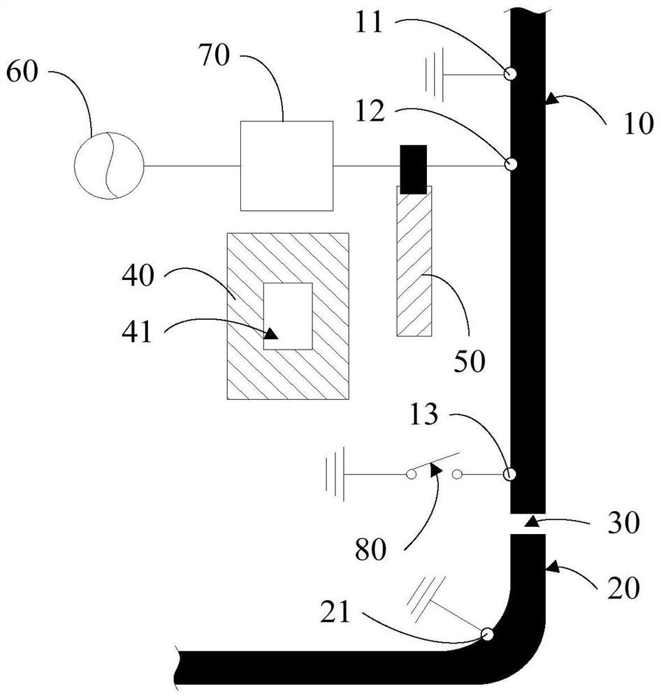
[0022] Such as figure 1 As shown, the embodiment of the present invention provides an antenna structure, including:

[0023] The first module, the first module includes a coupled first metal arm 10 and a second metal arm 20, a fracture 30 is arranged between the first metal arm 10 and the second metal arm 20, the first metal arm 10 includes a The first grounding point 11 at one end of the fracture 30, the second metal arm 20 includes a second groundin...


PUM


Abstract

The present invention provides an antenna structure and electronic equipment. The antenna structure includes: a first module, including a coupled first metal arm and a second metal arm, and a fracture is provided between the first metal arm and the second metal arm; The second module includes a coupled antenna patch and a feeding stub; a feeding source; a first matching circuit, the first end of the first matching circuit is electrically connected to the feeding source, and the second ends of the first matching circuit are electrically connected respectively The feed branch and the first feed point of the first metal arm, the first feed point is located between the fracture and the first grounding point; the first tuning switch, one end of the first tuning switch is grounded, and the other end is connected to the first metal arm The first connection point is electrically connected, the first connection point is located between the first feed point and the fracture; the first module is used to make the antenna structure work in the first frequency band, and the second module is used to make the antenna structure work in the first frequency band Two frequency bands, the first frequency band and the second frequency band are different. This can effectively reduce the difficulty of stacking the antenna structure.

Description

technical field [0001] The invention relates to the technical field of antennas, in particular to an antenna structure and electronic equipment. Background technique [0002] With the explosive growth of mobile user data volume, people have higher requirements for the speed and delay of mobile communication. The fifth generation (5th-Generation, 5G) mobile communication system can meet people's application requirements through more antennas, more frequency bands and wider bandwidth. [0003] At present, the two frequency bands mainly used in 5G communication include: FR1 frequency band and FR2 frequency band. Among them, the frequency range of the FR1 frequency band is 450 MHz to 6 GHz, and is also called the sub 6G frequency band; the frequency range of the FR2 frequency band is 24.25 GHz to 52.6 GHz, and is also called millimeter wave (mm Wave). In order to enable the antenna structure of the electronic device to cover the FR1 frequency band, it is necessary to set an an...

Claims


Application Information

Patent Timeline
Patent Type & Authority Patents(China)
IPC IPC(8): H01Q21/30
CPCH01Q21/30
Inventor 郑超
Owner VIVO MOBILE COMM CO LTD
Features
  • R&D
  • Intellectual Property
  • Life Sciences
  • Materials
  • Tech Scout
  • Unparalleled Data Quality
  • Higher Quality Content
  • 60% Fewer Hallucinations
Learn More