
Buckle Device

A buckle and buckle technology, applied in belt buckles, buckles, clothing and other directions, can solve the problems of insufficient durability, cumbersome assembly procedures, complex buckle structure, etc., and achieve the effect of prolonging the service life

Active Publication Date: 2020-07-21
BROGENT TECH
View PDF8 Cites 4 Cited by
  • Summary
  • Abstract
  • Description
  • Claims
  • Application Information

AI Technical Summary

Problems solved by technology

[0009] 1. Insufficient durability:
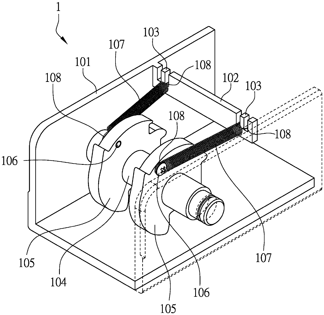
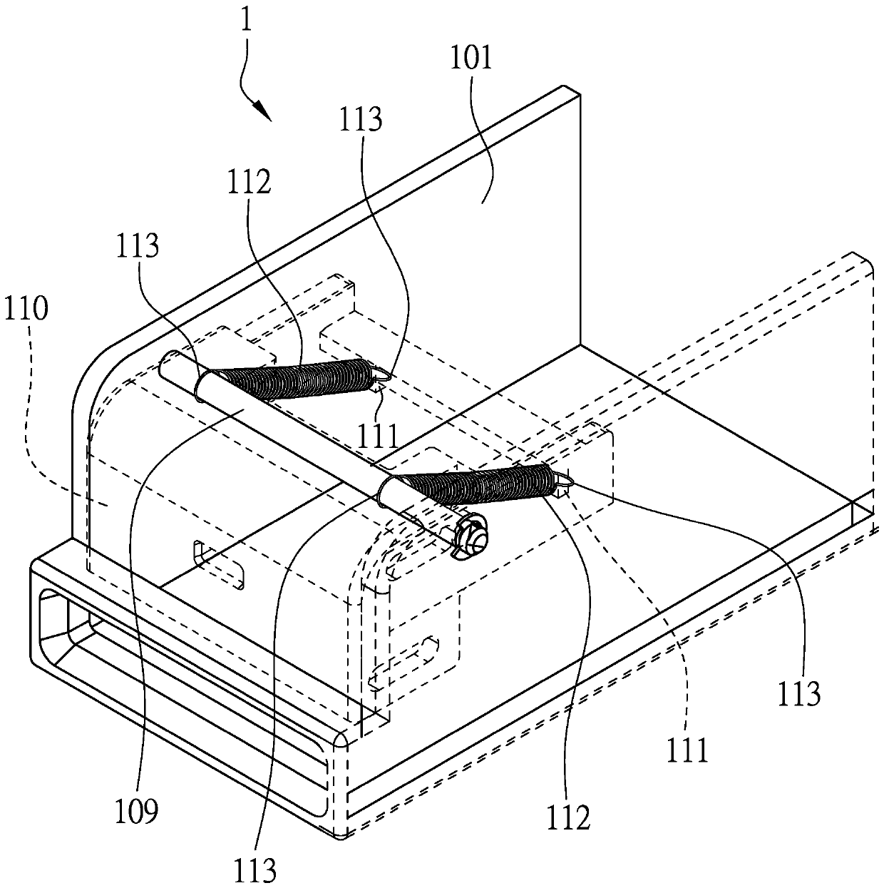
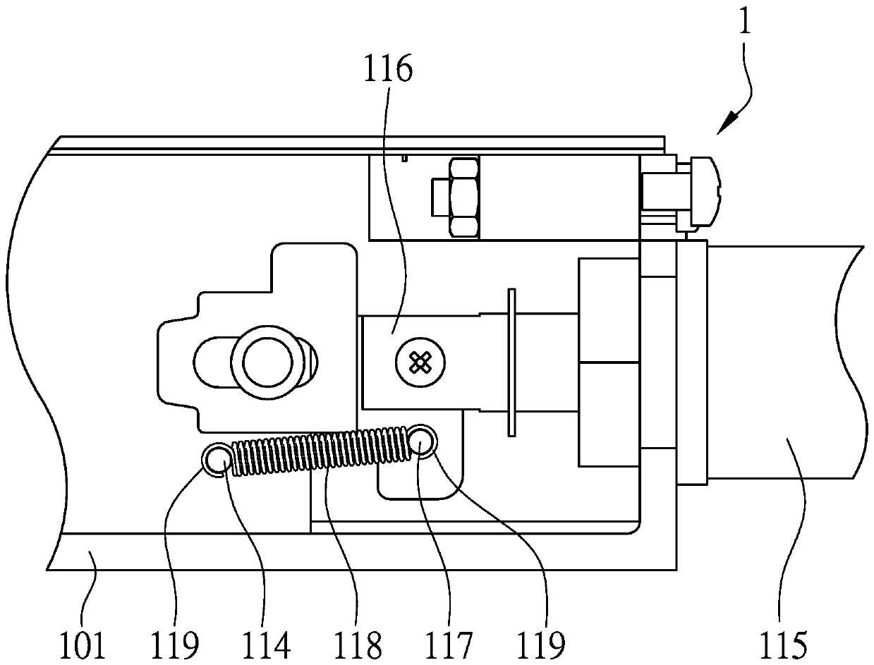
[0010] Due to the known use of tension springs, ring-shaped fasteners must be provided on both sides of the tension springs to fasten two objects and provide tension between the two objects, and the connection between the tension spring and the ring-shaped fasteners has a certain expansion and contraction effect. Breakage will occur after the number of times, and the durability is obviously insufficient
[0011] Second, the assembly procedure is cumbersome:
[0012] Continuing from the above, each fastener must fasten the connecting part on the object, and the fastener parts are complex, and must be assembled according to a fixed assembly procedure, which is cumbersome. For example, the known third horizontal column 109 not only needs The second buckle 113 provided with the second spring 112 is buckled, and must pass through the pressing body 110 to limit the range of movement of the pressing body 110, and the assembly of the parts is difficult
[0013] 3. Complex structure:
[0014] Each movable body must be provided with a spring and a fixture fixed to the housing. The known second connecting part 106 and fourth connecting part 117 are screw parts, and the first connecting part 103 and third connecting part 111 are convex structures. , and the number of springs used is large, and the structure of the known buckle is relatively complicated

Method used


Image

  • Buckle Device
  • Buckle Device
  • Buckle Device

Examples


Embodiment Construction

[0049] The present invention will be further described below in conjunction with the accompanying drawings and specific embodiments, so that those skilled in the art can better understand the present invention and implement it, but the examples given are not intended to limit the present invention.

[0050] refer to Figure 4 , is a preferred embodiment of a buckle device of the present invention, and the buckle device is suitable for being detachably combined with a buckle device 2 . The buckle device 2 is provided with a buckle body 21 .

[0051] In this preferred embodiment, the buckle device includes a main body unit 3 , two chuck units 4 , a press buckle unit 5 , two magnetic buckle units 6 , and an elastic force unit 7 .

[0052] The main unit 3 includes a buckle housing 32 surrounding and defining an accommodating space 31 , a buckle through hole 33 disposed in the buckle housing 32 , and a chuck support 34 disposed in the accommodating space 31 . A pressing support b...


PUM


Abstract

A buckle device comprises a main unit, a disk unit, a press unit, and an elastic unit. The main unit includes a housing. The disk unit includes at least one vertical disk. The press unit includes a press body. The elastic unit includes a first spring body. One end of the first spring body is disposed on the vertical disk. The other end of the first spring body is disposed on the press body. The first spring body is a thrust spring to extend the lifespan of the buckle device.

Description

technical field [0001] The invention relates to a buckle device, in particular to a buckle device arranged on a chair. Background technique [0002] Chairs with somatosensory features will be equipped with fixing straps and buckles to fix the human body on the chair, so as to prevent the human body from being thrown out when the chair provides somatosensory power. [0003] China Taiwan patent M473859 discloses a buckle 1 for seat belts, which can control the buckle combined with the buckle 1 from being opened by the person sitting on the seat, and further protect the seat when the seat provides somatosensory power. Person sitting in the seat. [0004] refer to figure 1 , the buckle 1 includes a first horizontal column 102 arranged in a housing 101, two first connecting parts 103 arranged in the first horizontal column 102, a second horizontal column arranged in a housing 101 104, two vertical chucks 105 pivotally arranged on the second cross column 104, two second connect...

Claims


Application Information

Patent Timeline
Patent Type & Authority Applications(China)
IPC IPC(8): A44B11/16
CPCA44B11/16A44B11/2523A44D2203/00A44B11/2534A44B11/2542A44B11/2573
Inventor 邱世光陈柏村陈瑞宗
Owner BROGENT TECH
Learn More