Steel rail telescopic regulator

A regulator and rail technology, which is applied to rail joints, rails, switches, etc., can solve the problems of unstable overall structure and easy eversion of the rail telescopic regulator 100', so as to reduce the difficulty of assembly, maintenance and repair. Expand the scope of use and expand the optional effect

Inactive Publication Date: 2020-07-24
CHINA RAILWAY CONSTR HEAVY IND
View PDF10 Cites 1 Cited by
  • Summary
  • Abstract
  • Description
  • Claims
  • Application Information

AI Technical Summary

Problems solved by technology

[0003] like figure 1 and figure 2 As shown, the current rail telescopic regulator 100' mainly adopts a structure in which the basic rail 104' is telescopic and the tip rail 106' is fixed. The basic rail brace 170' and the platform 132' buckle the basic rail 104'. In the state of the telescopic adjuster 100', the basic rail support 170' and the platen 132' must be able to effectively withhold the basic rail 104'. A certain gap should be reserved between the rail support 170' and the basic rail waist 156', and between the platform 132' and the base rail 104'. , easy to turn outward, making the overall structure of the rail telescopic adjuster 100' unstable

Method used


Image

  • Steel rail telescopic regulator
  • Steel rail telescopic regulator
  • Steel rail telescopic regulator

Examples


Embodiment 1

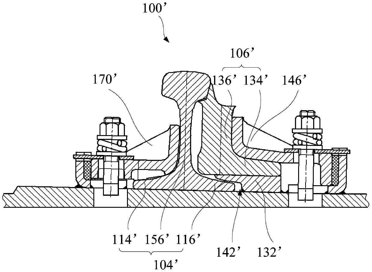
[0056] Such as image 3 and Figure 4 As shown, the embodiment of one aspect of the present invention proposes a rail telescopic adjuster 100, including: a backing plate 166, a base plate 102, a basic rail 104, a switch rail 106 and a telescopic assembly, wherein the backing plate 166 includes a bottom plate 102 and a second A platform 132, the first platform 132 is arranged above the bottom plate 102, the upper surface of the bottom plate 102 is inclined, the basic rail 104 is fixed on the bottom plate 102, at least part of the basic rail 104 is in a plurality of cross-sections perpendicular to the length direction of the basic rail The areas are not equal, the basic rail 104 includes the basic rail rail head; the switch rail 106 is arranged on the first platform 132, at least part of the switch rail 106 is located outside the basic rail 104, at least part of the switch rail 106 is perpendicular to the length direction of the switch rail The areas of the multiple cross-secti...

Embodiment 2

[0060] Such as Figure 3 to Figure 14 As shown, in one embodiment of the present invention, the rail telescopic adjuster 100 includes: a backing plate 166, a basic rail 104, a point rail 106, a telescopic assembly, a first limiting assembly 110 and a second limiting assembly 112, and the basic rail 104 It also includes a first basic rail leg 114 and a second basic rail leg 116 in contact with the bottom plate 102, the basic rail head includes a first basic rail head 118 disposed towards the switch rail, and the first basic rail leg 114 deviates from The switch rail 106 is set; wherein, the first limit assembly 110 abuts against the first basic rail limb 114 to limit the movement of the first basic rail limb 114 relative to the backing plate 166, and the second limit assembly 112 and the second basic rail The rail legs 116 abut against each other to limit the movement of the second basic rail leg 116 relative to the backing plate 166 .

[0061] In this example, if Figure 4 a...

Embodiment 3

[0067] Such as Figure 3 to Figure 14 As shown, the rail telescopic adjuster 100 provided by an embodiment of the present invention, on the basis of the above-mentioned embodiment 2, further, the first platform 132 is higher than the second basic rail limb 116, and the second limit assembly 112 Including: an elastic clip 140, the first plate 132 is provided with a mounting groove toward the side of the bottom plate 102, and the mounting groove is provided with an opening toward the side of the second basic rail leg 116, and one end of the elastic clip 140 passes through the opening and the second The basic rail rail limb 116 abuts, and the other end of the elastic clip 140 is connected with the first platform 132 on the side away from the opening; or the second limiting member is the first platform 132, and the first platform 132 faces the second basic One side of the rail limb 116 is provided with a platen bayonet 142 , and the platen bayonet 142 is adapted to the second basi...


PUM


Abstract

The invention provides a steel rail telescopic regulator. The steel rail telescopic regulator comprises: a base plate, wherein the base plate comprises a bottom plate and a first table plate, and theupper surface of the bottom plate is obliquely arranged; a stock rail fixed on the bottom plate, wherein at least part of the areas of a plurality of cross sections, perpendicular to the length direction of the stock rail, of the stock rail are unequal; a switch rail arranged on the first table plate, wherein at least part of the switch rail is located on the outer side of the stock rail, the areas of multiple cross sections, perpendicular to the length direction of the switch rail, of at least part of the switch rail are unequal, and the switch rail can telescopically move in the direction perpendicular to the length direction of the switch rail; and a telescopic assembly arranged on the first table plate, wherein the telescopic assembly is configured to be suitable for stretching out anddrawing back of the switch rail and enable at least part of the switch rail head to abut against the stock rail head. According to the steel rail telescopic regulator, the problems that an existing steel rail telescopic regulator is unstable in overall structure, and the stock rail is prone to turning outwards are solved, the assembling, maintaining and repairing difficulty is lowered, and the steel rail telescopic regulator is suitable for application and popularization.

Description

technical field [0001] The invention relates to the technical field of rail telescopic adjustment, in particular to a rail telescopic adjuster. Background technique [0002] The rail telescopic adjuster is one of the important track components of the railway. When laying seamless lines on long continuous beams of railways, it is usually necessary to set up rail telescopic adjusters. The function of the rail telescopic regulator is not only to allow the train to pass safely and smoothly at high speed, but also to coordinate the displacement difference between the telescopic displacement of the bridge end of the long bridge and the telescopic displacement of the long rail caused by temperature, so that the temperature of the long rail on the bridge can be automatically adjusted Force, thereby reducing the load on the track and bridge. [0003] Such as figure 1 and figure 2 As shown, the current rail telescopic regulator 100' mainly adopts a structure in which the basic ra...

Claims


Application Information

Patent Timeline
Patent Type & Authority Applications(China)
IPC IPC(8): E01B11/42E01B7/08E01B9/66
CPCE01B7/08E01B9/66E01B11/42
Inventor 刘皓刘伟罗震林志文刘培
Owner CHINA RAILWAY CONSTR HEAVY IND
Why Eureka
Try Eureka