Anti-loosening socket with indication function

An anti-loosening and indicating technology, which is applied to the parts of the connecting device, the device to prevent wrong connection, and the device to prevent contact with live contacts, etc. Tight insertion, poor contact between the plug and socket, etc., to achieve the effect of alleviating anxiety

Active Publication Date: 2020-07-24
林高龙
View PDF9 Cites 8 Cited by
  • Summary
  • Abstract
  • Description
  • Claims
  • Application Information

AI Technical Summary

Problems solved by technology

[0004] The purpose of the present invention is to solve the problem that the clamping force of the reed in the socket in the prior art will become smaller after long-term use, resulting in poor contact between the plug and the socket, and people cannot intuitively judge whether the plug is inserted tightly when using the socket. The shortcomings that need to be pressed or re-plugged by hand can be determined, but a kind of anti-loosening socket with indicating function is proposed

Method used


Image

  • Anti-loosening socket with indication function
  • Anti-loosening socket with indication function
  • Anti-loosening socket with indication function

Examples


Embodiment 1

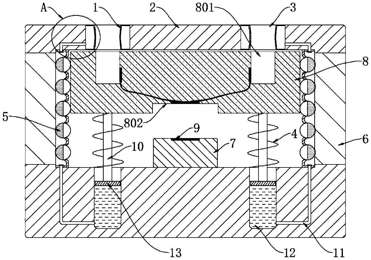
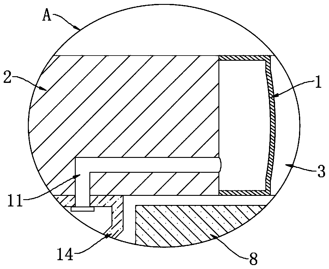
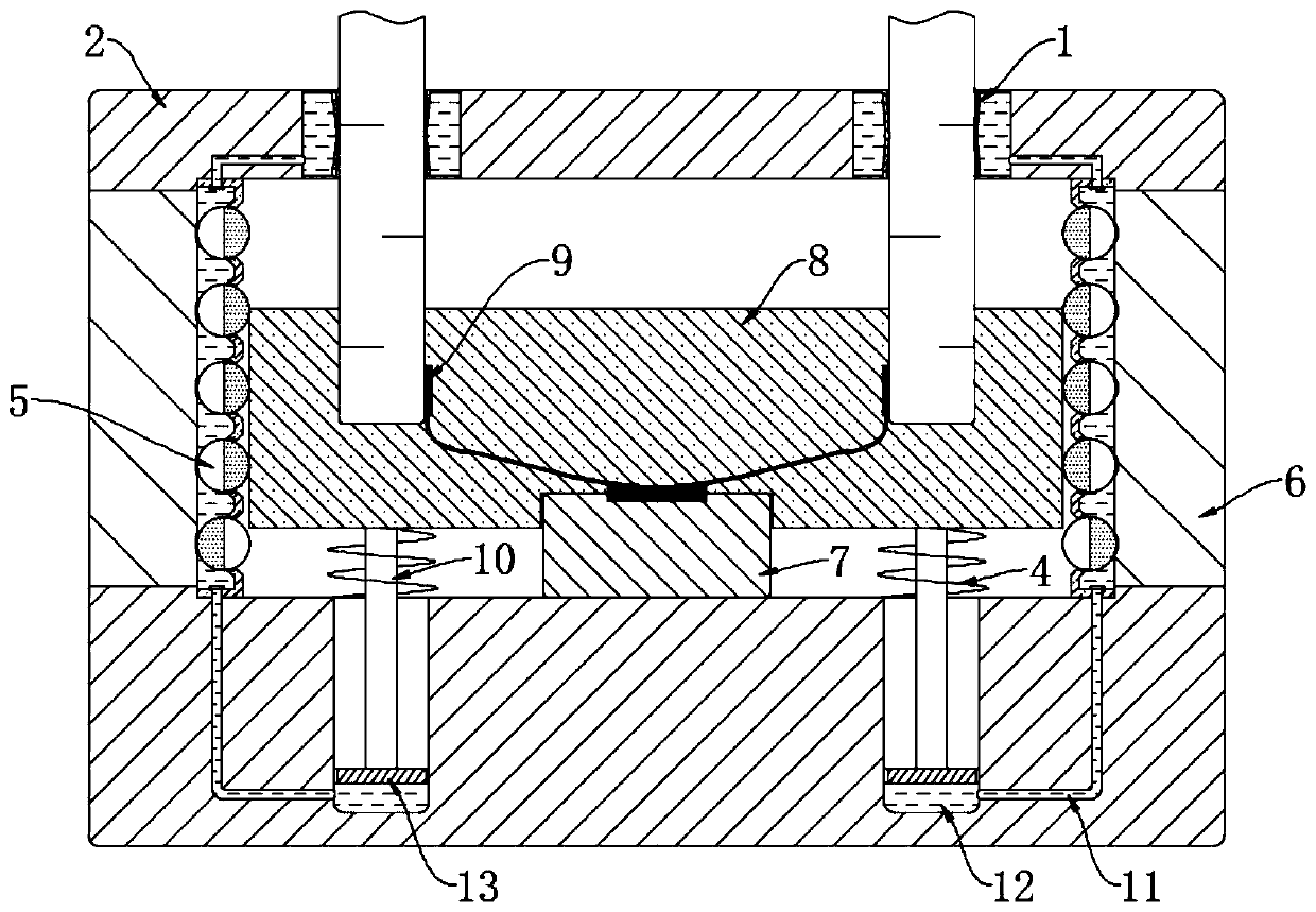
[0030] refer to Figure 1-4 , an anti-loosening socket with an indicating function, comprising a socket body 2, a socket 3 is symmetrically opened on the socket body 2, and a groove body is opened in the socket body 2, and two fixing brackets 14 are symmetrically installed in the groove body, and A plurality of indicator balls 5 are installed in rotation on each fixed frame 14, and the indicator balls 5 and the fixed frame 14 are connected to each other in a sealed rotation, and a connecting plate 8 is arranged between the two fixed frames 14, and two of the connecting plates 8 The side walls are in rolling contact with the corresponding indicator balls 5, and a plurality of heat dissipation fins 6 are symmetrically embedded on the side walls of the socket body 2, and the plurality of heat dissipation fins 6 on the same side and the corresponding fixing frame 14 jointly form a A sealed cavity, an observation window 15 is sealed between two adjacent heat dissipation fins 6, whi...

Embodiment 2

[0042] refer to Figure 5-6 The difference between this embodiment and Embodiment 1 is that: the socket body 2 is provided with an adjustment groove 19 communicating with the two fasteners 1, and a rubber plate 17 is arranged for sealing and sliding in the adjustment groove 19, and the rubber plate 17 is far away from the tightening One side of the fastener 1 is fixedly connected with a push-pull piece 16 , and the push-pull piece 16 is located outside the socket body 2 .

[0043] In this embodiment, a baffle 18 is integrally formed in the middle of the adjustment groove 19, and the baffle 18 is hollow cylindrical. The baffle 18 can limit the moving distance of the push-pull part 16, but cannot stop the flow of liquid.

[0044] When using this embodiment, when the plug is inserted, the non-electrolyte will flow into the adjustment tank 19, push the push-pull part 16 toward the socket body 2 until the rubber plate 17 and the baffle 18 are in contact, and the fastener 1 will be ...


PUM


Abstract

The invention discloses an anti-loosening socket with an indication function. The socket comprises a socket body, jacks are symmetrically arranged on the socket body, and a groove body is arranged inthe socket body; two fixing frames are symmetrically mounted in the groove body; a plurality of indicating balls are rotatably mounted on each fixing frame; and a connecting plate is arranged betweenthe two fixing frames, two side walls of the connecting plate are connected with the corresponding indication balls in a rolling mode, a plurality of cooling fins are symmetrically embedded in the side walls of the socket body, and the multiple cooling fins located on the same side and the corresponding fixing frames jointly form a sealed cavity. After a plug is completely inserted, the color of the indication balls changes, a user can judge whether the plug is tightly inserted or not by observing the color change, and after the plug is inserted into the socket body, fasteners at the jacks extrude a metal sheet on the plug so that connection between the plug and the socket body is more stable, and the plug is not easy to loosen.

Description

technical field [0001] The invention relates to the field of power connection, in particular to an anti-loosening socket with indicating function. Background technique [0002] Socket is a relatively common tool for power connection in daily life. Some sockets are fixed on the wall to facilitate power supply for large electrical appliances such as TVs, water heaters, and refrigerators. , which saves space and is easy to move. [0003] The common socket realizes the elastic clamping of the plug through the reed, but as the number of plugging and unplugging increases, the clamping force of the reed will become smaller, resulting in poor contact between the plug and the socket. If a larger elastic force is used during production In addition, some patients with obsessive-compulsive disorder always have to repeatedly pull out the plug or press the plug repeatedly because they are worried that the plug is not inserted tightly. In order to reduce people's anxiety and make the plug...

Claims


Application Information

Patent Timeline
Patent Type & Authority Applications(China)
IPC IPC(8): H01R13/641H01R13/639H01R13/44H01R13/527H05K7/20
CPCH01R13/44H01R13/527H01R13/639H01R13/641H05K7/20218H05K7/2039
Inventor 马启福
Owner 林高龙
Why Eureka
Try Eureka