Surgical auxiliary rehabilitation system
A technology of surgery and supporting parts, which is applied in the field of surgical auxiliary rehabilitation system, can solve the problem of not being able to provide rehabilitation training for patients, and achieve the effect of facilitating rehabilitation training
- Summary
- Abstract
- Description
- Claims
- Application Information
AI Technical Summary
Problems solved by technology
Method used
Image
Examples
Embodiment 1
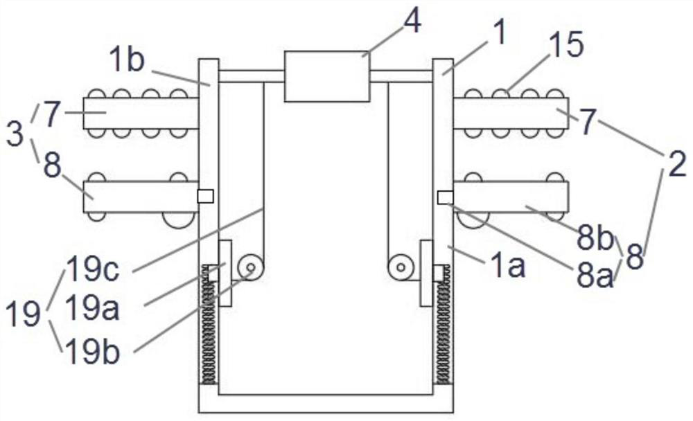
[0046] Such as Figure 1 to Figure 7 As shown, the present application provides a surgical auxiliary rehabilitation system, which at least includes a housing 1 , a first support part 2 , a second support part 3 and a massage part 4 . The casing 1 , the first support part 2 and the second support part 3 can all support the user's feet. The massaging part 4 can massage the sole of the foot placed on the casing 1 . Both the first support part 2 and the second support part 3 can massage the sole and the instep of the foot placed thereon. For example, the housing 1 can be hollow, so that the massage part 4 can be disposed in the housing 1 . When it is necessary to massage the soles of the feet, the user only needs to put his legs into the casing 1 and make the soles of his feet touch the massage part 4 . The first supporting part 2 is disposed on the first side 1 a of the housing 1 . The first supporting part 2 can support the user's first foot when the user's second foot is pl...
Embodiment 2
[0058] This embodiment is a further improvement on Embodiment 1, and repeated content will not be repeated here.
[0059] preferred, such as figure 1 As shown, the first foot or the second foot can move along the first direction and enter the space between the second support rod 7 and the first support rod 8, so that the instep is in contact with the second support rod 7, and the sole of the foot It is in contact with the first support rod 8 . For example, if figure 2 As shown, the first direction can be a horizontal right direction. When the first foot or the second foot moves a set distance in the first direction, the first support rod 8 can move based on the external force exerted by the sole of the foot. Specifically, the first support rod 8 can slide along the first sliding groove 10 or the second sliding groove 11 . When the first foot or the second foot moves along the first direction, the first support rod 8 can move along the second sliding groove 11 in a manner ...
Embodiment 3
[0063] This embodiment is a further improvement on the foregoing embodiments, and repeated content will not be repeated here.
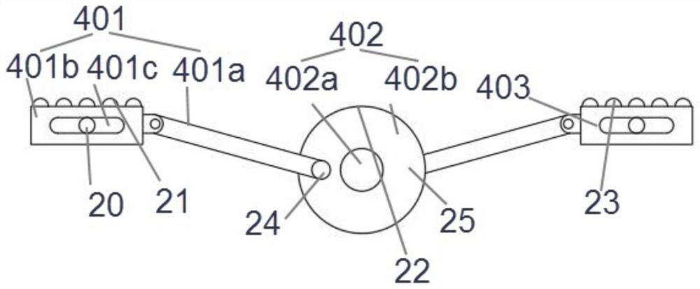
[0064] Preferably, when the user's sole is in contact with the massage part 4 , at least a first contact point 21 , a second contact point 22 and a third contact point 23 can be formed between the sole of the user's foot and the massage part 4 . The first contact point 21 can be formed by the abutting contact between the massage slider 401b corresponding to the first massage mechanism 401 and the sole of the foot. The second contact point 22 can be formed by the abutting contact between the massage wheel 402b and the sole of the foot. The third contact point 23 can be formed by the abutting contact between the massage slider 401b corresponding to the third massage mechanism 403 and the sole of the foot.
[0065]Preferably, for ease of description, the hinge point between the first massage mechanism 401 and the massage wheel 402b is named as the first...
PUM
 Abstract
Description
Claims
Application Information
 - R&D
- Intellectual Property
- Life Sciences
- Materials
- Tech Scout
- Unparalleled Data Quality
- Higher Quality Content
- 60% Fewer Hallucinations
Browse by: Latest US Patents, China's latest patents, Technical Efficacy Thesaurus, Application Domain, Technology Topic, Popular Technical Reports.
© 2025 PatSnap. All rights reserved.Legal|Privacy policy|Modern Slavery Act Transparency Statement|Sitemap|About US| Contact US: help@patsnap.com


