Operating mechanism of automatic change-over switching device

A technology of automatic transfer switch and operating mechanism, which is applied in the direction of contact drive mechanism and power device inside the switch, etc. It can solve the problems of instability, potential safety hazards, and inability to ensure that the main and backup power sources are disconnected at the same time, so as to achieve convenient installation, The effect of improving stability

Pending Publication Date: 2020-07-28
RADIN ELECTRIC TECH
View PDF1 Cites 0 Cited by
  • Summary
  • Abstract
  • Description
  • Claims
  • Application Information

AI Technical Summary

Problems solved by technology

The operating mechanism controls the linkage shaft to move quickly in the arc track through the spring mechanism, so as to realize the rapid switching of the operating mechanism between the main and backup power sources, but the operating mechanism cannot be positioned accurately at the station where the main and backup power sources are disconnected Ensure that the main and backup power supply are disconnected at the same time, there is a certain degree of instability and a certain potential safety hazard

Method used


Image

  • Operating mechanism of automatic change-over switching device
  • Operating mechanism of automatic change-over switching device
  • Operating mechanism of automatic change-over switching device

Examples


Embodiment Construction

[0021] The present invention will be further described below in conjunction with the accompanying drawings.

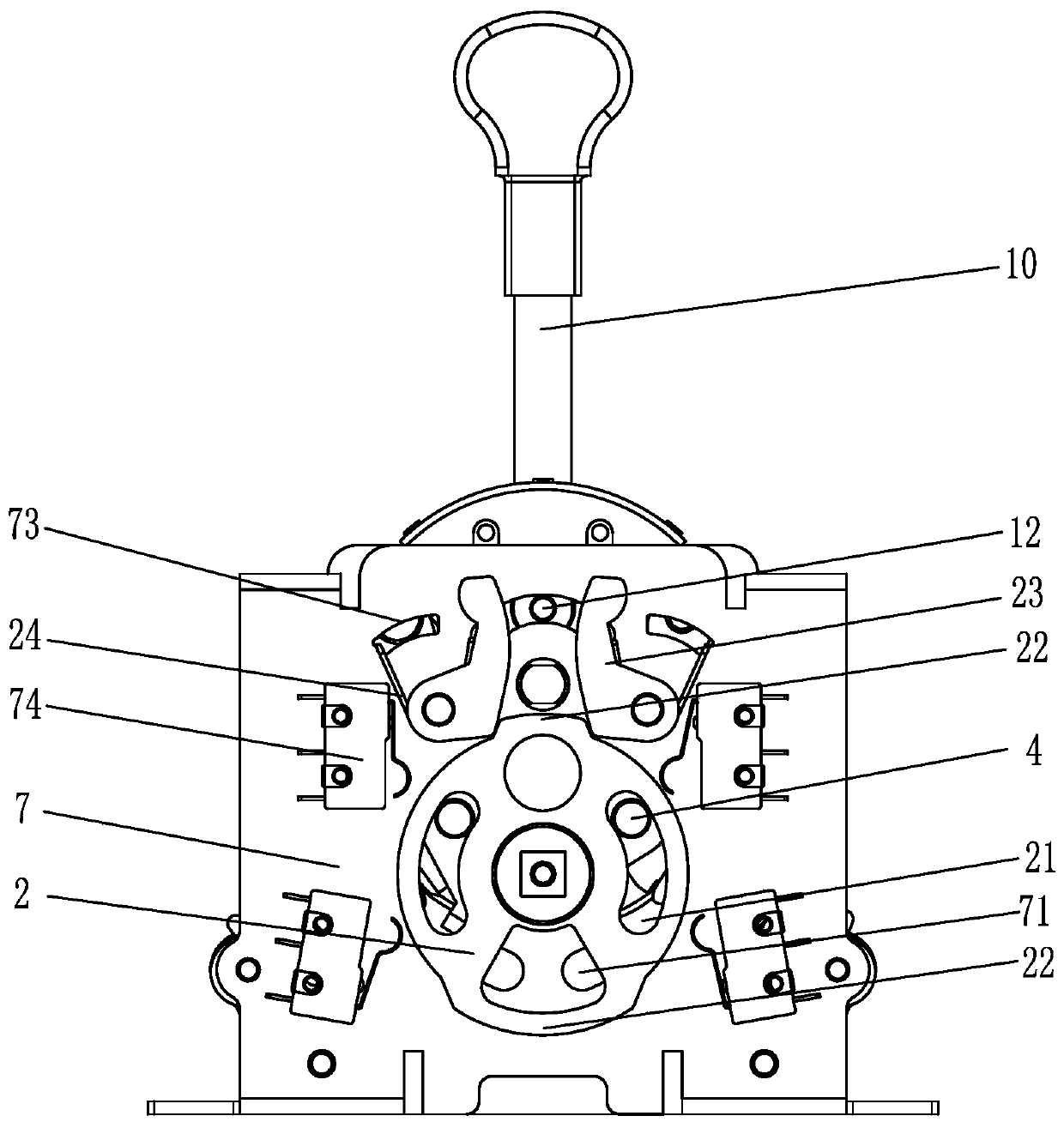
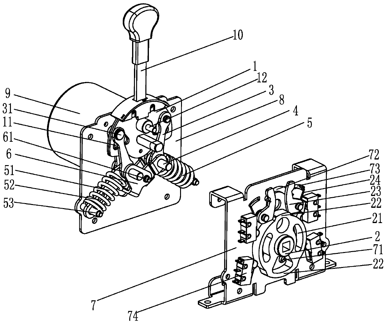
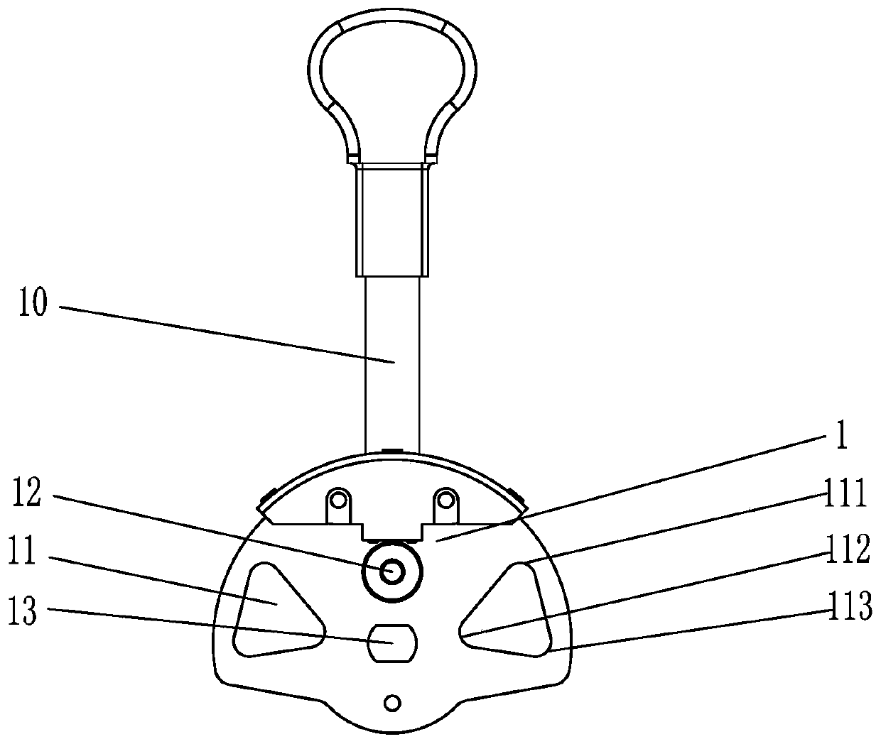
[0022] Such as Figure 1-Figure 3 As shown, the specific embodiment of the present invention is an operating mechanism for an automatic transfer switch appliance, including a mechanism bracket, a rotating plate 1, a rotating disk 2, a connecting rod 3, a drive shaft 4, a spring 5, a rotating arm 6, and a motor 9. The mechanism bracket is spliced ​​by the mechanism front plate 7 and the mechanism rear plate 8. The rotating plate 1 is arranged between the mechanism front plate 7 and the mechanism rear plate 8. The upper end of the rotating plate 1 is provided with a handle 10, and the motor 9 is arranged on the mechanism rear plate 8. On the outside, a special-shaped central hole 13 is formed in the center of the rotating plate 1, and the output shaft of the motor 9 fits through the central hole 13 in the rotating plate 1. The rotating disk 2 is arranged outside the fron...


PUM


Abstract

The invention relates to an operating mechanism of an automatic change-over switching device. The operating mechanism comprises a rotating plate, a rotating disc, connecting rods, driving shafts, springs and rotating arms, wherein the two driving shafts are respectively arranged at the outer ends of the two connecting rods in a penetrating manner, the outer ends of the two connecting rods are respectively connected with the outer ends of the two rotating arms, the inner ends of the two rotating arms are connected to a central shaft, the inner ends of the springs are connected with the outer ends of the connecting rods, the outer ends of the springs are fixed, two triangular holes are symmetrically formed in the rotating plate, the inner ends of the two connecting rods are respectively connected into the two triangular holes, a rotating plate column is arranged at the inner end of the connecting rod, the rotating plate column moves in the triangular hole, two arc-shaped driving groovesare formed in the rotating disc, and the two driving shafts penetrate through the two driving grooves respectively. According to the invention, a moving space is provided for the rotating plate columnof the connecting rod through the triangular hole, so that the rotating plate column can rapidly move in the triangular hole in the switching process so as to achieve the rapid skipping among all gears of the automatic change-over switch.

Description

technical field [0001] The invention relates to an operating mechanism of an automatic transfer switching device, in particular to an operating mechanism of an automatic transfer switching device capable of accurately realizing simultaneous disconnection of main and standby power sources. Background technique [0002] The automatic transfer switch controls the connection of the main and backup power sources through the operating mechanism. In order to reduce production costs, more and more operating mechanisms use single-axis output, that is, a square shaft is used to control the brake contact to switch between the main and backup power sources. . For example, the publication number CN109411256A discloses the operating mechanism of the dual-power automatic transfer switch, including a fixed shaft, an input turntable, a linkage shaft, an output turntable, and a spring mechanism. There are two input slots, the edge of the output turntable forms two output slots corresponding ...

Claims


Application Information

Patent Timeline
Patent Type & Authority Applications(China)
IPC IPC(8): H01H3/32H01H3/38H01H3/26
CPCH01H3/26H01H3/32H01H3/38
Inventor 张彭春吴利军银引森洪洋
Owner RADIN ELECTRIC TECH
Why Eureka
Try Eureka