Steel bar bending machine

A technology of a steel bar bending and bending device, which is applied in the field of steel bar processing, can solve the problems of affecting the use of steel bars, reducing the quality accuracy of steel bar bending, and low quality accuracy of steel bar bending, and achieves the effect of saving driving force and reducing energy consumption.

Active Publication Date: 2020-07-31
浙江礼显试验仪器制造有限公司
View PDF7 Cites 3 Cited by
  • Summary
  • Abstract
  • Description
  • Claims
  • Application Information

AI Technical Summary

Problems solved by technology

[0002] The steel bar bending machine is a special equipment for bending the straightened and cut steel bar into the required size and shape. After the "U" shape bending is performed on the steel bar, the bent steel bar is placed on the plane, and one end of the steel bar is It will warp and affect the use of subsequent steel bars. That is, if the existing steel bar bending machine is used to process steel bars, the quality and accuracy of steel bar bending processing will be low. When multiple steel bars are bent at the same time, the steel bar bending quality accuracy will be reduced again.

Method used


Image

  • Steel bar bending machine
  • Steel bar bending machine
  • Steel bar bending machine

Examples


Embodiment Construction

[0018] In order to enable those skilled in the art to better understand the solutions of the present invention, the technical solutions in the embodiments of the present invention will be clearly and completely described below in conjunction with the drawings in the embodiments of the present invention. Obviously, the described embodiments are only It is a part of embodiments of the present invention, but not all embodiments. Based on the embodiments of the present invention, all other embodiments obtained by persons of ordinary skill in the art without making creative efforts shall fall within the protection scope of the present invention.

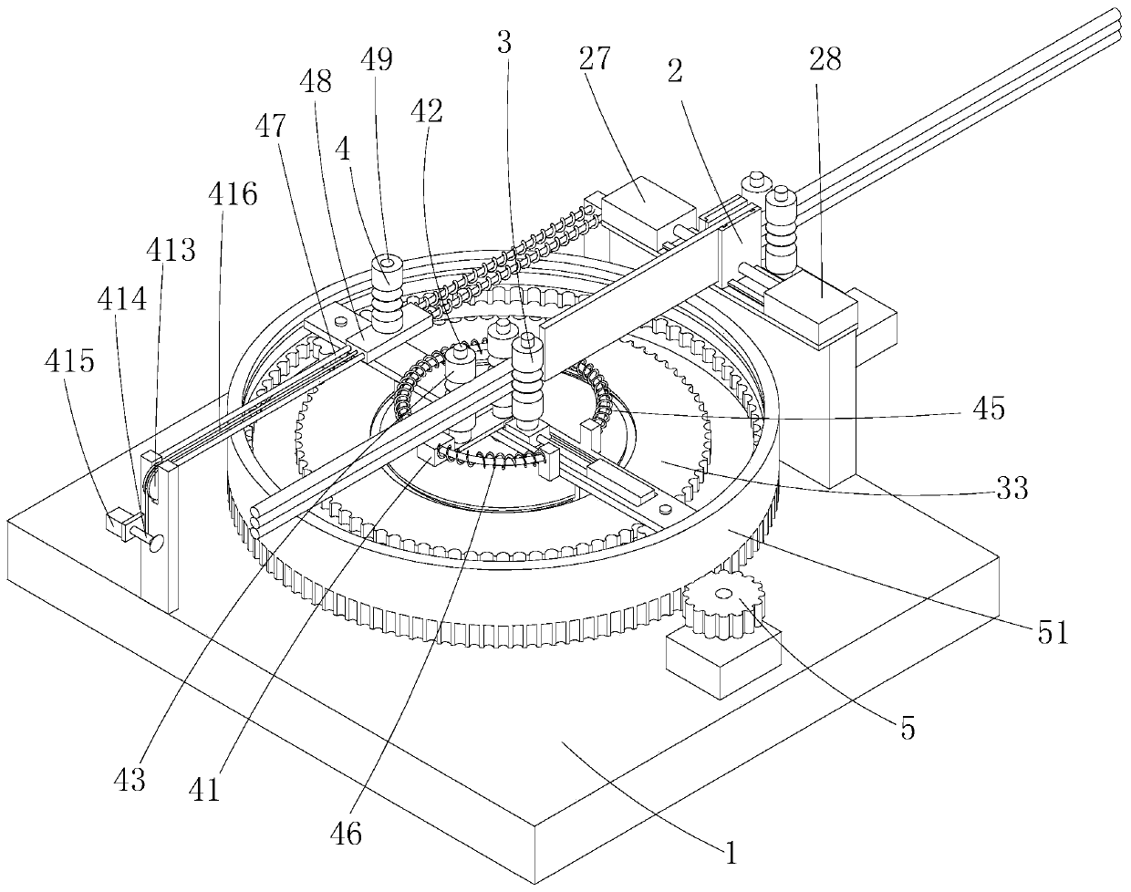
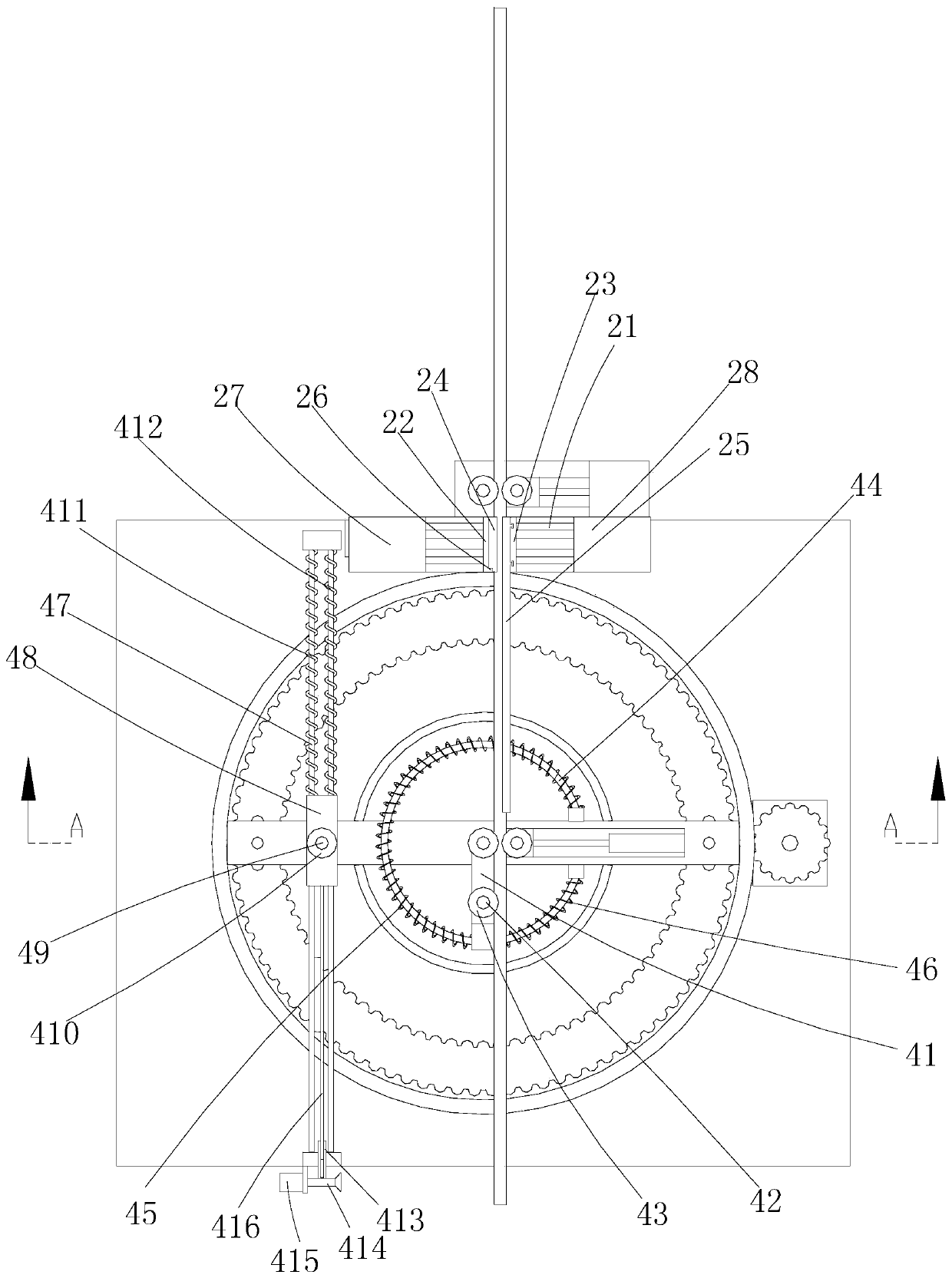
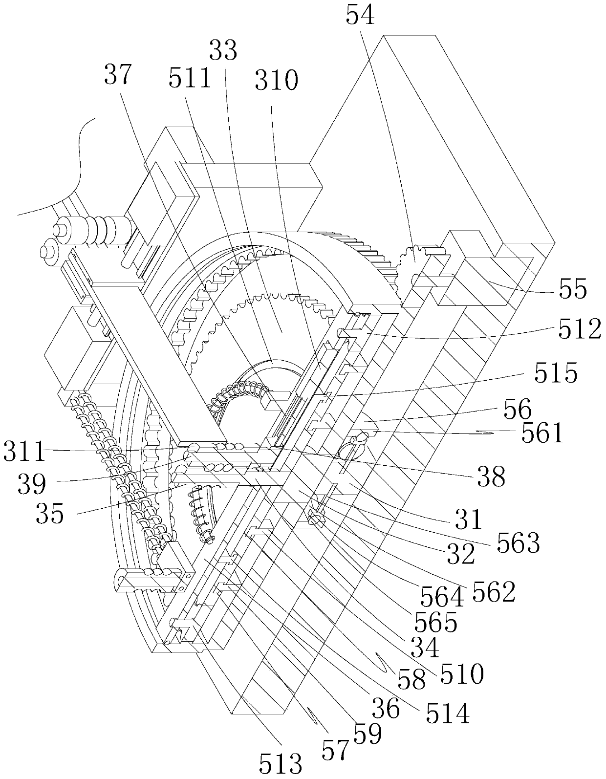
[0019] Such as Figure 1-8 As shown, the steel bar bending machine includes a body 1, a fixing device 2 arranged on the body, a bending device 3 for bending steel bars, an auxiliary device 4 for assisting steel bar bending, and a power device 5 arranged on the body The fixing device 2 includes a first slide rail 21, a first slide seat 22...


PUM


Abstract

The invention discloses a steel bar bending machine. The steel bar bending machine comprises a machine body, a fixing device arranged on the machine body, a bending device used for bending steel bars,an auxiliary device used for assisting in bending of the steel bars, and a power device arranged on the machine body, wherein the fixing device is provided with a first clamping plate and a second clamping plate; the first clamping plate is provided with a plurality of first arc-shaped grooves; the second clamping plate is provided with a plurality of second arc-shaped grooves; and the bending device is provided with a first fixing shaft, a first sleeve roller rotationally arranged on the first fixing shaft in a sleeving manner, a rotating base rotationally arranged on the first fixing shaftin a sleeving manner, a first T-shaped sliding groove formed in the rotating base, a first T-shaped sliding block movably arranged on the first T-shaped sliding groove, a second fixing shaft fixedly arranged on the first T-shaped sliding block, a third hydraulic cylinder used for driving the first T-shaped sliding block to move, and a second sleeve roller rotationally arranged on the second fixingshaft in a sleeving manner. The steel bar bending machine can be used for bending the multiple steel bars at the same time, the quality precision of the bent steel bars is high, and subsequent usageof the steel bars is facilitated.

Description

technical field [0001] The invention relates to the technical field of steel bar processing, in particular to a steel bar bending machine. Background technique [0002] The steel bar bending machine is a special equipment that bends the straightened and cut steel bar into the required size and shape. After the "U" shape bending is performed on the steel bar, the bent steel bar is placed on the plane, and one end of the steel bar is It will warp and affect the use of subsequent steel bars. That is, if the existing steel bar bending machine is used to process steel bars, the quality and accuracy of steel bar bending processing will be low. When multiple steel bars are bent at the same time, the steel bar bending quality accuracy will be reduced again. Contents of the invention [0003] In order to overcome the deficiencies of the prior art, the present invention provides a steel bar bending machine, which can bend multiple steel bars at the same time. The bent steel bars hav...

Claims


Application Information

Patent Timeline
Patent Type & Authority Applications(China)
IPC IPC(8): B21F1/00
CPCB21F1/00
Inventor 沈一炯段烛明陈国平肖云飞王明旭
Owner 浙江礼显试验仪器制造有限公司
Why Eureka
Try Eureka