
Lift type foundation structure

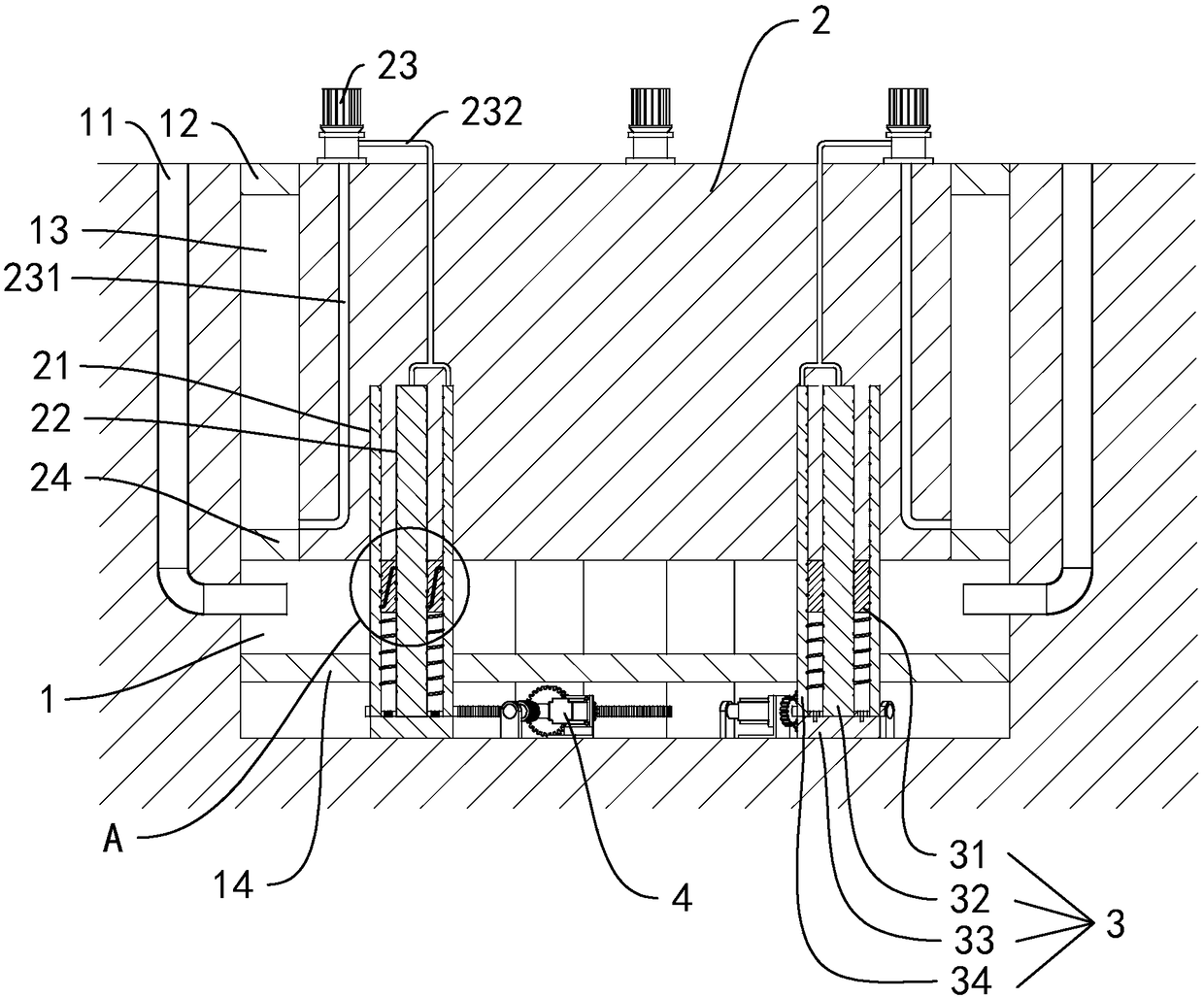
A lifting and lifting structure technology, which is applied in the direction of basic structure engineering, excavation, construction, etc., can solve the problems of heavy load of dynamic structure and can not achieve labor-saving effect, so as to reduce load, drive the foundation to rise with labor-saving, and the connection structure is reasonable and stable. Effect

Active Publication Date: 2018-07-10
华洲建设温州有限公司
View PDF8 Cites 1 Cited by
  • Summary
  • Abstract
  • Description
  • Claims
  • Application Information

AI Technical Summary

Problems solved by technology

[0004] In the above technical solution, the drive gear is used to drive the rack to move vertically to drive the foundation up and down, but the quality of the foundation and the house built on the foundation is relatively large, and the linear speed of the gear and the speed of the rack during the rotation of the rack-and-pinion transmission structure The speed is the same, the rack and pinion transmission cannot achieve the effect of labor saving, resulting in excessive load of the power structure providing the drive

Method used


Image

  • Lift type foundation structure
  • Lift type foundation structure
  • Lift type foundation structure

Examples


Embodiment Construction

[0034] The present invention will be further described in detail below in conjunction with the drawings.

[0035] The same or similar reference numerals in the drawings of the embodiments of the present invention correspond to the same or similar components; in the description of the present invention, it should be understood that if there are the terms "upper", "lower", "left", "right" The orientation or positional relationship of other indications is based on the orientation or positional relationship shown in the drawings, which is only used to facilitate the description of the present invention and simplify the description, and does not indicate or imply that the device or element referred to must have a specific orientation and a specific orientation. The azimuth structure and operation, therefore, the terms describing the positional relationship in the drawings are only used for exemplary description and cannot be understood as a limitation of the patent. For those of ordina...


PUM


Abstract

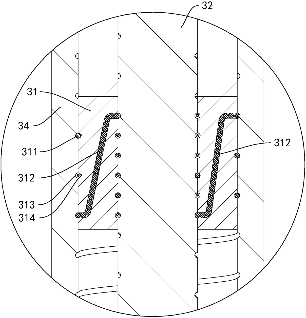
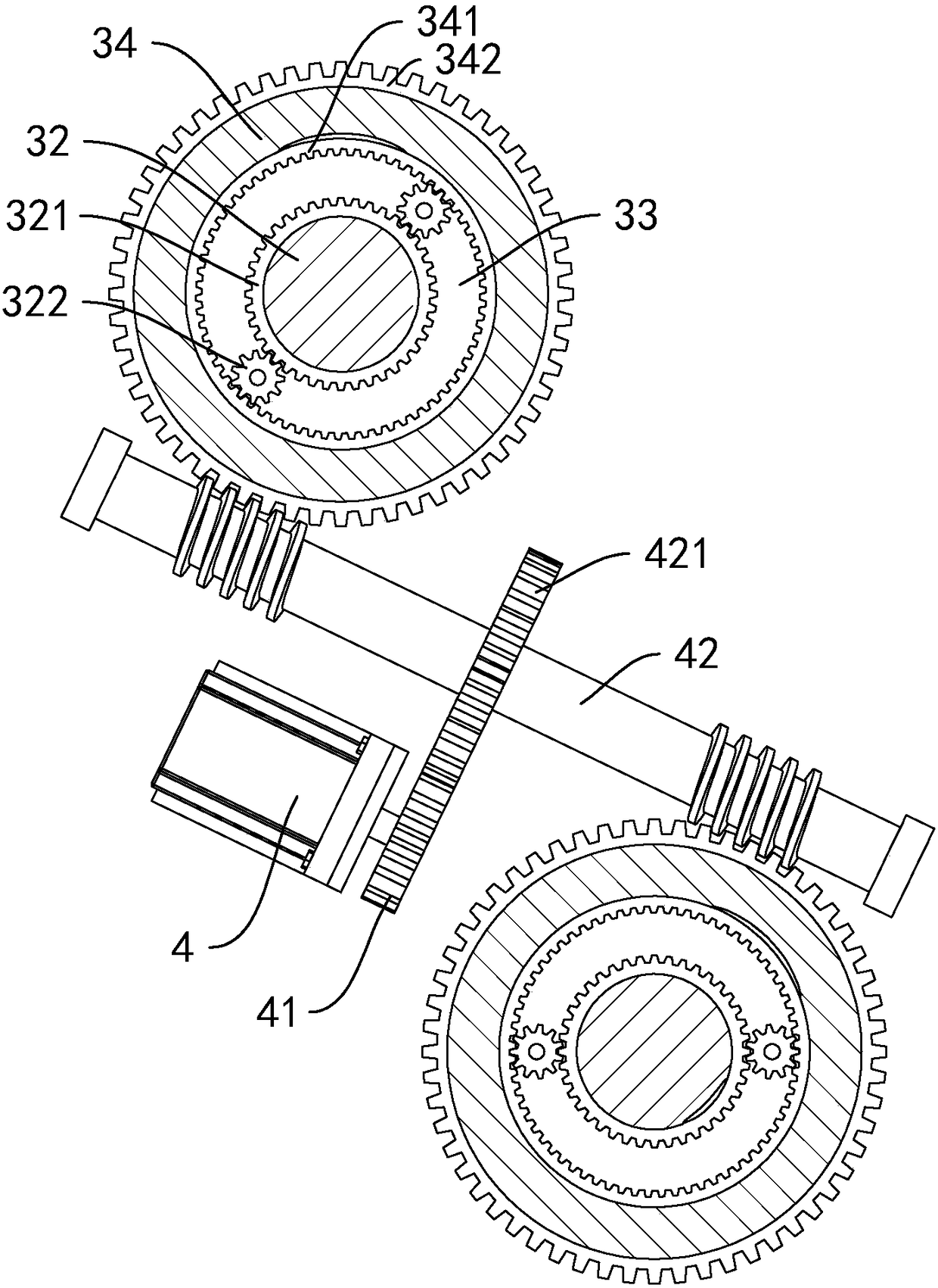
The invention discloses a lift type foundation structure, belongs to the field of foundations and solves the problem that a power structure providing driving has overlarge load because gear and rack transmission cannot achieve a labor saving effect. The lift type foundation structure comprises a deep pit which is formed in the bottom surface; a foundation is arranged inside the deep pit; lifting structures are arranged at the bottom of the deep pit; each lifting structure comprises a screw rod, sliding sleeves, a screw barrel and a hydraulic motor; the sliding sleeves are placed on the corresponding screw rods in a sleeving manner and are in treaded connection with the corresponding screw rods; the screw barrels are placed on each other in a sleeving manner and are in threaded connection with each other; the hydraulic motor is used for driving the screw barrels and the screw rods to rotate. The lift type foundation structure disclosed by the invention is reasonable in structure, achieves a labor saving effect by generating axial motion and relatively large axial force by virtue of relatively small torque rotation by using helical transmission, and reduces the load of the hydraulicmotor.

Description

Technical field [0001] The present invention relates to a foundation, and more specifically, it relates to a lifting type foundation structure. Background technique [0002] In cities, houses are built on lower ground. When the amount of precipitation is large, the urban ground will be submerged, which will affect the lives of residents. For this purpose, a lift-type foundation structure is provided, and when the amount of precipitation is large, the house will rise to prevent being submerged by water. [0003] At present, the Chinese invention patent application with publication number CN106567401A discloses a lifting foundation structure, including a deep pit opened on the ground, the side wall and bottom of the deep pit are provided with a waterproof layer, and the building foundation is set in the deep pit; The ground is provided with a water inlet communicating with the bottom of the deep pit; a driving mechanism is embedded in the ground, and the driving mechanism includes a...

Claims


Application Information

Patent Timeline
Patent Type & Authority Applications(China)
IPC IPC(8): E02D27/32E02D17/02
CPCE02D17/02E02D27/32
Inventor 林安周
Owner 华洲建设温州有限公司
Learn More