
An installation base structure for protection and transfer of electrical automation equipment

A technology for electrical automation and installation of bases, which is used in electrical equipment structural parts, electrical equipment casings/cabinets/drawers, electrical components, etc. Short circuit and other problems to achieve the effect of reducing the adjustment resistance

Inactive Publication Date: 2021-05-28
王来印
View PDF11 Cites 0 Cited by
  • Summary
  • Abstract
  • Description
  • Claims
  • Application Information

AI Technical Summary

Problems solved by technology

[0005] In order to solve the above-mentioned technical problems, the present invention provides a mounting base structure for the protection and transfer of electrical automation equipment, to solve the problem that the above-mentioned electrical automation equipment must have a stable power supply when it is used, and the voltage stabilizing equipment is inconvenient to observe and adjust in time. In the case of overload or short circuit, it cannot be checked and repaired in time. The poor heat dissipation of the circuit instrument will affect the normal operation of the instrument, and the stability of the automation equipment is low when it is running, and it is inconvenient to carry.

Method used


Image

  • An installation base structure for protection and transfer of electrical automation equipment
  • An installation base structure for protection and transfer of electrical automation equipment
  • An installation base structure for protection and transfer of electrical automation equipment

Examples


Embodiment

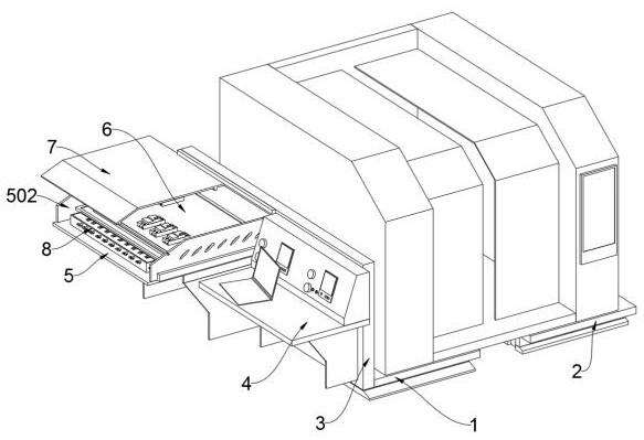
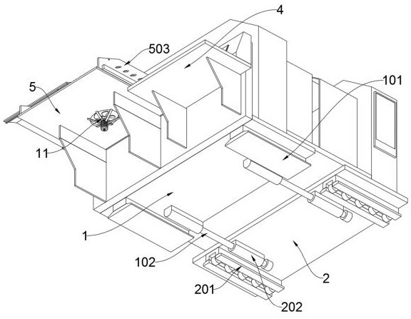
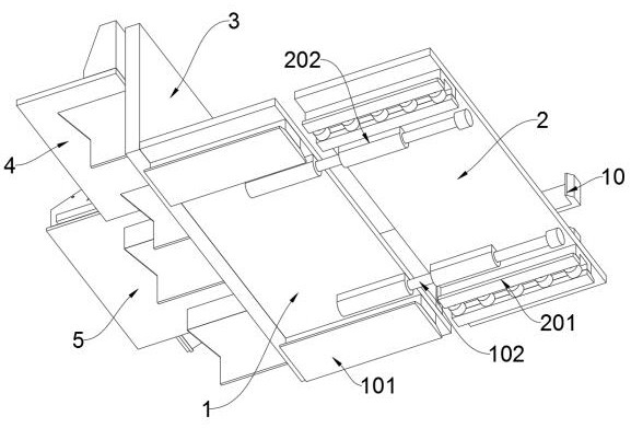
[0034] as attached figure 1 to attach Figure 9 Shown:

[0035] The invention provides an installation base structure for the protection and transfer of electrical automation equipment, including a front base 1, a rear base 2, a workbench 4, a voltage stabilizing platform 5, a grid plate 6, an explosion-proof cover 7, and a wiring groove 8. Telescopic frame 9, hook bar mechanism 10, fan 11; the front of front base 1 is fixedly connected with front partition 3; rear base 2 is movably connected to the rear of front base 1; telescopic frame 9 is connected to the side of front base 1 by welding; Hook fence mechanism 10 is movably connected on telescopic frame 9, and hook fence mechanism 10 includes guide rod two 1001, positioning plate 1002 and internal tooth groove 10021, and one end on the surface of hook fence mechanism 10 is connected with guide rod two 1001 by welding, and positioning The plate 1002 is slidingly connected to the two guide rods 1001 through clearance fit; th...


PUM


Abstract

The invention provides an installation base structure for the protection and transfer of electrical automation equipment, including a front base, a rear base, a workbench, a voltage stabilizing platform, a grid plate, an explosion-proof cover, a wiring groove, a telescopic frame, and a hook rail mechanism. fan; the front of the front base is fixedly connected with a front partition; the rear base is movably connected to the rear of the front base; the telescopic frame is connected to the side of the front base by welding; the hook bar mechanism is movably connected to the telescopic frame Above, the hook bar mechanism includes a guide rod two, a positioning plate and an inner tooth groove, and one end of the surface of the hook bar mechanism is connected with a guide bar two by welding, and the positioning plate is slidingly connected at two places through clearance fit. on the second pole; the workbench is fixedly connected to the front surface of the front bulkhead; the voltage stabilizing platform is fixedly connected to the front surface of the front bulkhead, and the voltage stabilizing platform is located on the left side of the workbench; the power supply module is improved The stability of power supply and the function of easy inspection and maintenance can improve the stability of equipment operation.

Description

technical field [0001] The invention belongs to the technical field of installation base equipment, and more specifically relates to an installation base structure used for the protection and transfer of electrical automation equipment. Background technique [0002] Large-scale complete sets of equipment in the automation system, also known as automation devices. It refers to the process in which a machine or device is automatically operated or controlled according to a prescribed procedure or instruction without human intervention. Therefore, automation is an important condition and a significant symbol of the modernization of industry, agriculture, national defense and science and technology. When the automation equipment is running, it needs to have a sufficiently stable power supply, a stable installation environment and correct operating specifications. Therefore, in order to ensure the normal operation of the automation equipment , providing a base device with power c...

Claims


Application Information

Patent Timeline
Patent Type & Authority Patents(China)
IPC IPC(8): H05K5/02H05K7/20H05K7/00
CPCH05K5/0213H05K5/0217H05K5/0234H05K7/005H05K7/20136
Inventor 王来印王润泽
Owner 王来印
Learn More