

Telescopically adjustable cargo tray
A telescopic adjustment and pallet technology, applied to rigid containers, containers, packaging, etc., can solve the problems of large space occupation, size change, high production materials and transportation costs, and achieve the effect of low load bearing and high stability
- Summary
- Abstract
- Description
- Claims
- Application Information
AI Technical Summary
Problems solved by technology
Method used
Image

Examples
Embodiment 1
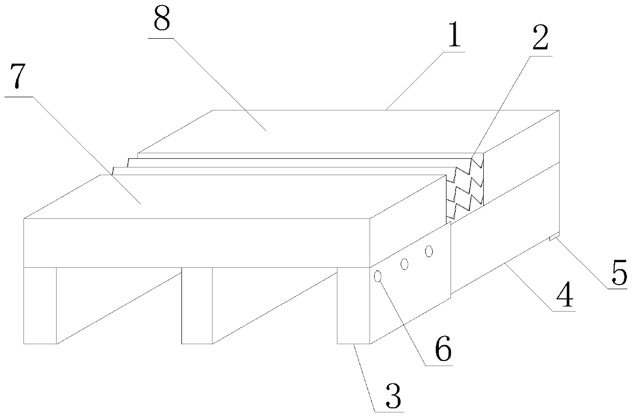
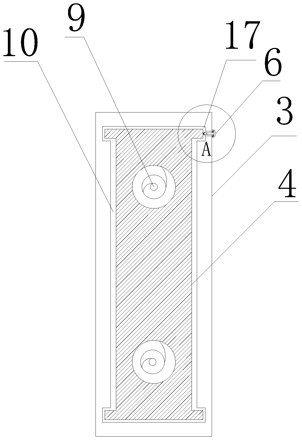
[0028] Such as Figure 1-3 As shown, a telescopically adjustable cargo pallet includes a pallet body 1 and a plurality of support plates supported on the bottom of the pallet body 1;
[0029] The front disc body 7 and the rear disc body 8 of the tray body 1 are connected by a telescopic connector 2;
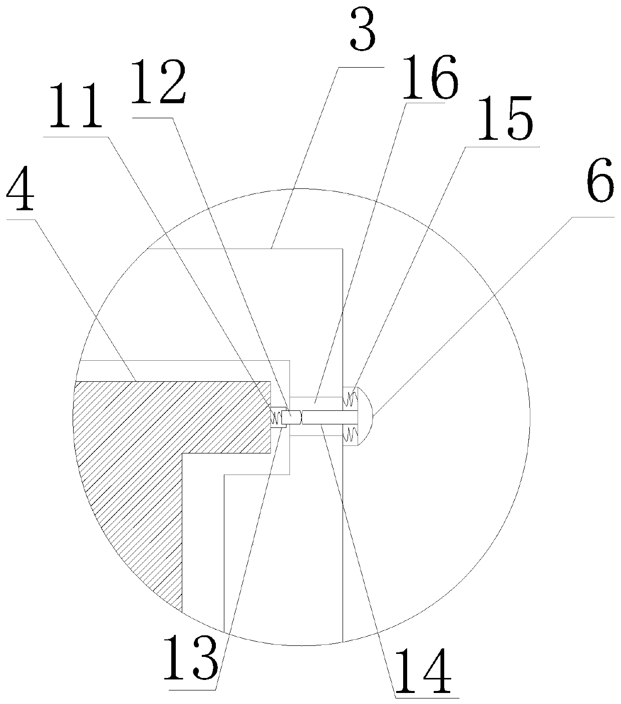
[0030] The front support plate 3 and the rear support plate 4 of the supporting plate are shown. The front support plate 3 is provided with a cavity 10 with one side opening, and the upper and lower ends of the two side walls of the cavity 10 are provided with sliding grooves 17. The rear support plate 4 One end of the sliding groove 17 is slidably connected to the sliding groove 17 inside the cavity body 10, and the bottom of the other end is provided with a supporting foot 5, and both ends of the sliding groove 17 are provided with blocks for clamping the rear support plate 4;
[0031] The front disc body 7 is fixed on the front support plate 3 , and the rear disc body 8 is fi...
Embodiment 2
[0034] Such as Figure 1-3 As shown, a telescopic adjustable cargo pallet is characterized in that: it includes a pallet body 1 and a plurality of support plates supported on the bottom of the pallet body 1;
[0035] The front disc body 7 and the rear disc body 8 of the tray body 1 are connected by a telescopic connector 2;
[0036] The front support plate 3 and the rear support plate 4 of the support plate are provided with a cavity 10 with an opening on one side inside the front support plate 3, and the upper and lower ends of the two side walls of the cavity 10 are provided with sliding grooves 17, and the rear support plate 4 One end is slidably connected to the sliding groove 17 inside the cavity 10, the bottom of the other end is provided with a supporting foot 5, and both ends of the sliding groove 17 are provided with blocks for clamping the rear support plate 4;
[0037] The front disc body 7 is fixed on the front support plate 3 , and the rear disc body 8 is fixed o...
PUM
 Abstract
Description
Claims
Application Information