
A power cable with a detachable mounting bracket

A technology for installing brackets and power cables, which is applied in the field of power cables and can solve the problems of troublesome loading and unloading, troublesome inspection and maintenance, and single installation and fixing method.

Inactive Publication Date: 2021-03-16
广东欣意合金科技有限责任公司
View PDF6 Cites 0 Cited by
  • Summary
  • Abstract
  • Description
  • Claims
  • Application Information

AI Technical Summary

Problems solved by technology

In order to facilitate the normal use of urban subways, cables for power supply and signal transmission need to be laid inside the subway tracks. At present, most of the cables used in urban subways have simple structures, and the installation and fixing methods are very single, and loading and unloading are troublesome, which makes later inspection and maintenance more troublesome.

Method used


Image

  • A power cable with a detachable mounting bracket
  • A power cable with a detachable mounting bracket
  • A power cable with a detachable mounting bracket

Examples


Embodiment Construction

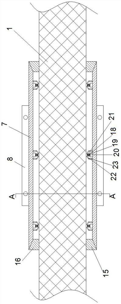
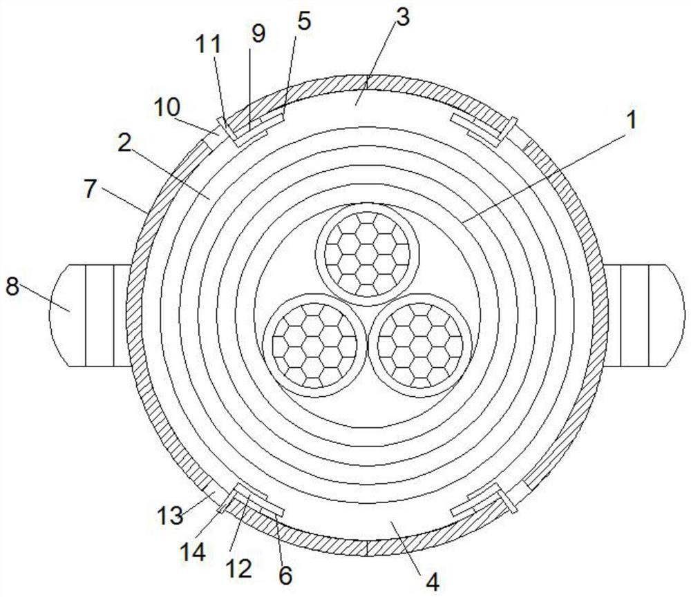
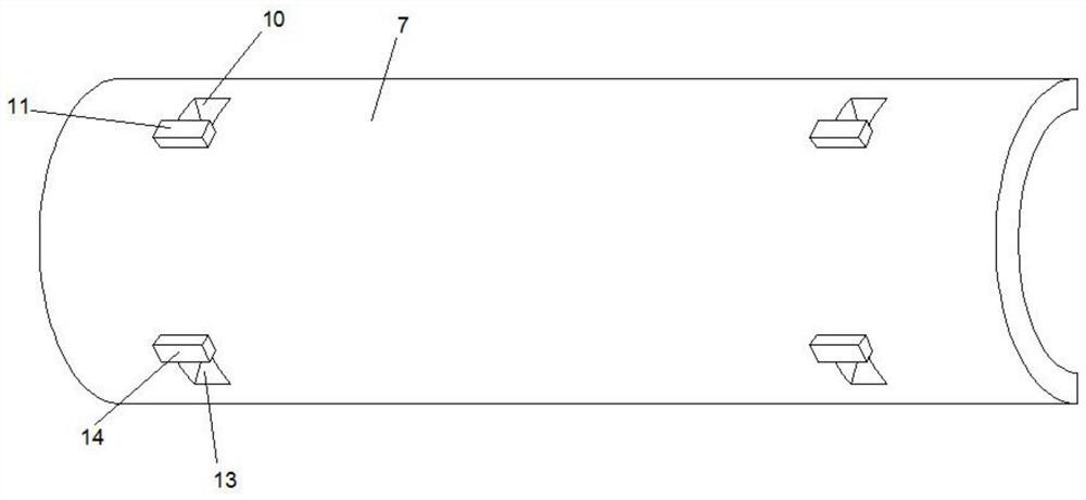
[0018] refer to Figure 1-Figure 4 , the present invention proposes a power cable with a detachable mounting bracket, including a cable body 1 and a mounting bracket; wherein:

[0019] The outside of the cable body 1 is wrapped with an outer sheath 2, and the outside of the outer sheath 2 is provided with a first connection platform 3 and a second connection platform 4 symmetrically arranged about the center of the cable body 1, and both sides of the first connection platform 3 are provided with its own The end faces a first card slot 5 extending inside, and both sides of the second connecting platform 4 are provided with second card slots 6 extending from its end face to its inside.

[0020] The mounting bracket includes two mounting sleeves 7 , the two mounting sleeves 7 are oppositely arranged on both sides of the cable body 1 and the ends of the two mounting sleeves 7 abut against each other, and a mounting plate 8 with screw holes is provided on the outside of the mountin...


PUM


Abstract

The invention provides a power cable with a detachable mounting bracket. The power cable comprises a cable body and the mounting bracket; a first connecting table and a second connecting table are arranged on the outer side of the outer sheath on the outer side of the cable body; first clamping grooves are formed in the two sides of the first connecting table, and second clamping grooves are formed in the two sides of the second connecting table; the mounting bracket comprises two mounting sleeves, and mounting plates with screw holes are arranged on the outer sides of the mounting sleeves; afirst clamping plate capable of being clamped into a first clamping groove is arranged on the inner side of each mounting sleeve; first sliding holes are formed in the two ends of the side, close to afirst clamping plate, of each mounting sleeve; first shifting blocks are connected into the first sliding holes in a sliding fit mode, and the first shifting blocks extend inwards to be connected with the first clamping plates; a second clamping plate capable of being clamped into a second clamping groove is arranged on the inner side of each mounting sleeve; second sliding holes are formed in the two ends of the side, close to a second clamping plate, of each mounting sleeve; second shifting blocks are connected into the second sliding holes in a sliding fit mode, and the second shifting blocks extend inwards to be connected with the second clamping plates. The power cable is simple in structure, and greatly facilitates the later maintenance and replacement of the cable.

Description

technical field [0001] The invention relates to the technical field of cables, in particular to a power cable with a detachable mounting bracket. Background technique [0002] The subway is an urban rail transit system that covers various underground and above-ground right-of-way proprietary, high-density, and high-capacity urban rail transit systems. In order to facilitate the normal use of urban subways, cables for power supply and signal transmission need to be laid inside the subway tracks. At present, most of the cables used in urban subways have simple structures, and the installation and fixing methods are very single, which makes loading and unloading troublesome, resulting in troublesome later inspection and maintenance. Contents of the invention [0003] Based on the technical problems in the background technology, the present invention proposes a power cable with a detachable mounting bracket. [0004] The present invention proposes a power cable with a detacha...

Claims


Application Information

Patent Timeline
Patent Type & Authority Patents(China)
IPC IPC(8): H02G3/04F16F15/067
CPCF16F15/067H02G3/0406
Inventor 朱昀
Owner 广东欣意合金科技有限责任公司
Learn More