Yarn waxing equipment for textile processing

A textile and yarn technology, applied in the field of yarn waxing equipment for textile processing, can solve the problems of uneven waxing and insufficient yarn waxing, and achieve comprehensive waxing, uniform waxing, and uniform wax distribution. Effect

Active Publication Date: 2020-08-07
抚州市中小企业服务有限公司
View PDF7 Cites 1 Cited by
  • Summary
  • Abstract
  • Description
  • Claims
  • Application Information

AI Technical Summary

Problems solved by technology

[0003] In order to overcome the shortcomings of insufficient comprehensive and uneven waxing of yarns in the prior art, the technical problem to be solved is: to provide a kind of waxing equipment for textile processing yarns with comprehensive and uniform waxing

Method used


Image

  • Yarn waxing equipment for textile processing
  • Yarn waxing equipment for textile processing
  • Yarn waxing equipment for textile processing

Examples


Embodiment 1

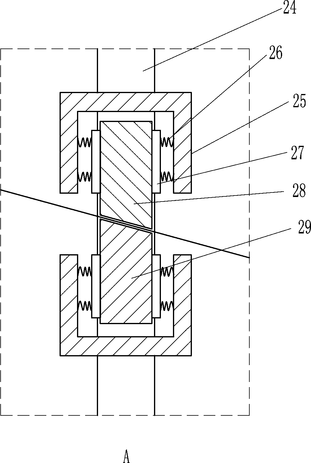
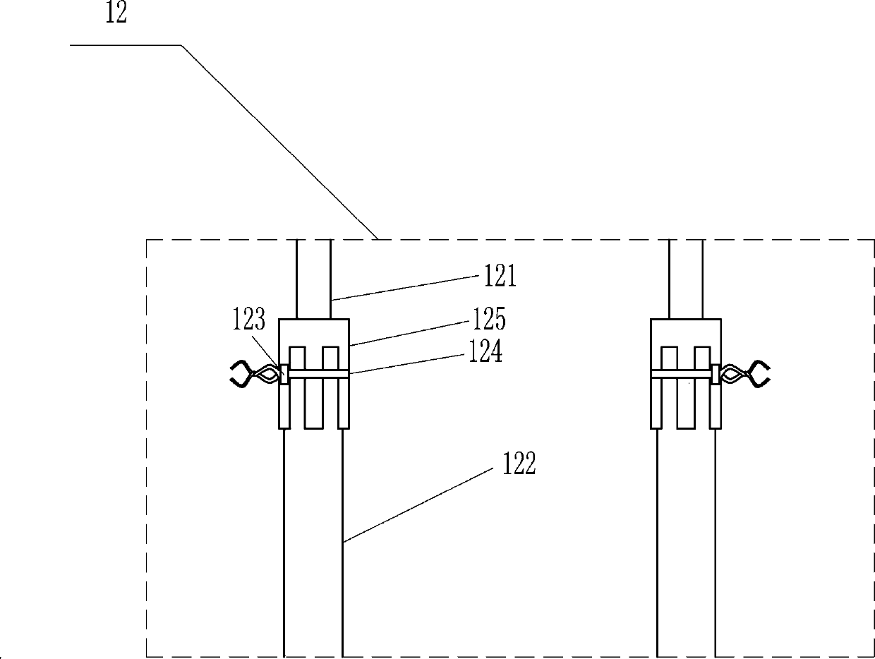
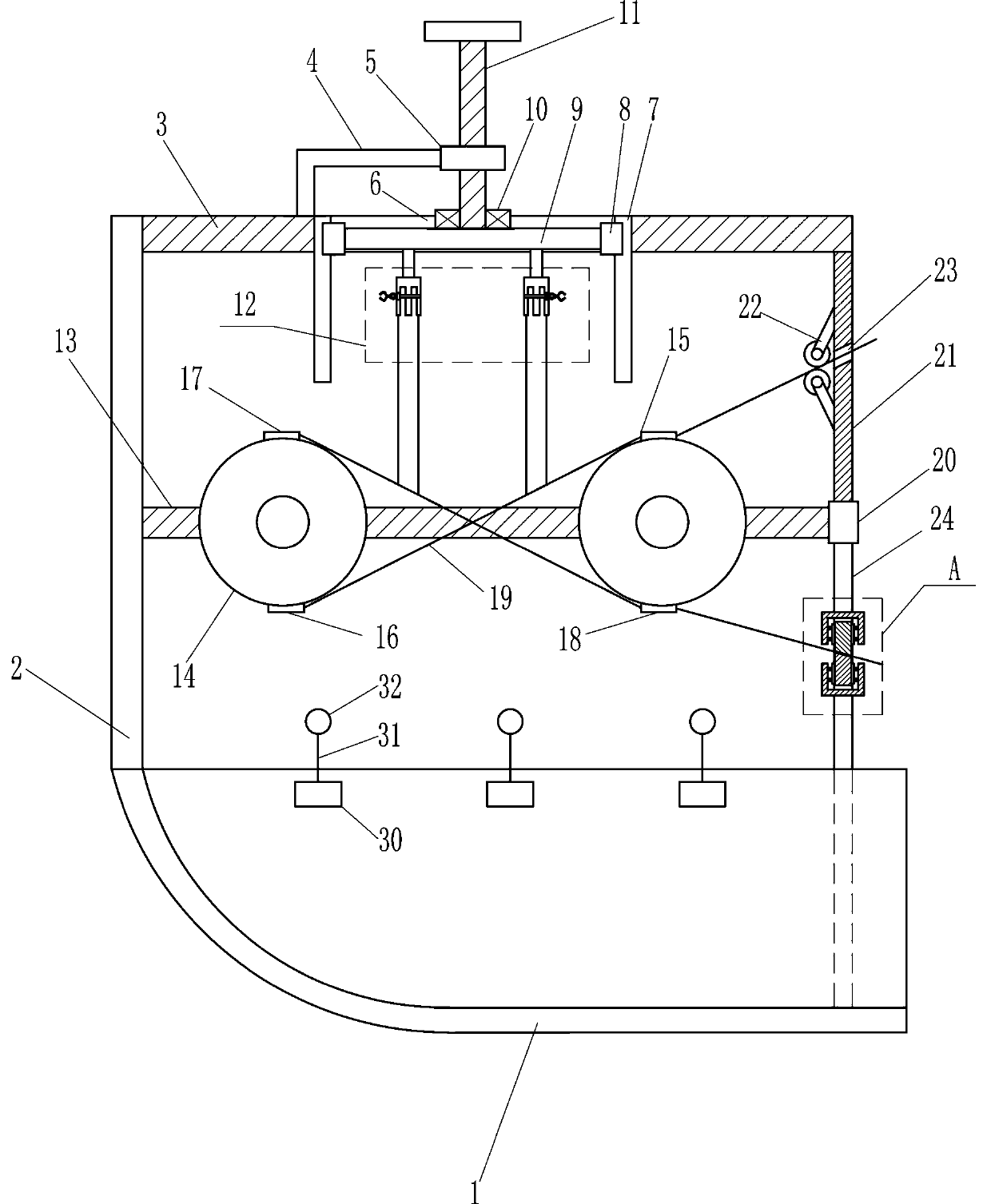
[0020] A kind of yarn waxing equipment for textile processing, such as Figure 1-4 As shown, it includes a collection frame 1, a support plate 2, a mounting plate 3, an L-shaped rod 4, a nut 5, a slide rail 7, a slider 8, a moving plate 9, a bearing seat 10, a screw 11, a fixing mechanism 12, a first Support rod 13, wire passing wheel 14, first chute 15, second chute 16, third chute 17, fourth chute 18, second support rod 20, third support rod 21 and roller 22, collection frame 1 The top of the left wall is provided with a support plate 2, the upper end of the right side of the support plate 2 is provided with a mounting plate 3, the left side of the top of the mounting plate 3 is provided with an L-shaped rod 4, the right end of the L-shaped rod 4 is provided with a nut 5, and the nut 5 is equipped with Screw rod 11, the first through hole 6 is opened in the middle of the mounting plate 3, the L-shaped rod 4 is located on the left side of the first through hole 6, the nut 5 i...

Embodiment 2

[0022] A kind of yarn waxing equipment for textile processing, such as Figure 1-4As shown, it includes a collection frame 1, a support plate 2, a mounting plate 3, an L-shaped rod 4, a nut 5, a slide rail 7, a slider 8, a moving plate 9, a bearing seat 10, a screw 11, a fixing mechanism 12, a first Support rod 13, wire passing wheel 14, first chute 15, second chute 16, third chute 17, fourth chute 18, second support rod 20, third support rod 21 and roller 22, collection frame 1 The top of the left wall is provided with a support plate 2, the upper end of the right side of the support plate 2 is provided with a mounting plate 3, the left side of the top of the mounting plate 3 is provided with an L-shaped rod 4, the right end of the L-shaped rod 4 is provided with a nut 5, and the nut 5 is equipped with Screw rod 11, the first through hole 6 is opened in the middle of the mounting plate 3, the L-shaped rod 4 is located on the left side of the first through hole 6, the nut 5 is...

Embodiment 3

[0025] A kind of yarn waxing equipment for textile processing, such as Figure 1-4 As shown, it includes a collection frame 1, a support plate 2, a mounting plate 3, an L-shaped rod 4, a nut 5, a slide rail 7, a slider 8, a moving plate 9, a bearing seat 10, a screw 11, a fixing mechanism 12, a first Support rod 13, wire passing wheel 14, first chute 15, second chute 16, third chute 17, fourth chute 18, second support rod 20, third support rod 21 and roller 22, collection frame 1 The top of the left wall is provided with a support plate 2, the upper end of the right side of the support plate 2 is provided with a mounting plate 3, the left side of the top of the mounting plate 3 is provided with an L-shaped rod 4, the right end of the L-shaped rod 4 is provided with a nut 5, and the nut 5 is equipped with Screw rod 11, the first through hole 6 is opened in the middle of the mounting plate 3, the L-shaped rod 4 is located on the left side of the first through hole 6, the nut 5 i...


PUM


Abstract

The invention relates to yarn waxing equipment, in particular to yarn waxing equipment for textile processing. The technical problem to be solved is to provide the yarn waxing equipment for textile processing, which is comprehensive and uniform in waxing. According to the technical scheme, the yarn waxing equipment for textile processing comprises a collecting frame, a supporting plate, a mountingplate, an L-shaped rod, a nut, a sliding rail, a sliding block, a moving plate, a bearing seat, a screw, a fixing mechanism, a first supporting rod, a yarn passing wheel and the like; the supportingplate is arranged at the top of a left wall of the collecting frame, the mounting plate is arranged at an upper end of a right side of the supporting plate, the L-shaped rod is arranged on a left sideof the top of the mounting plate, the nut is arranged at a right end of the L-shaped rod, and the screw is matched to the nut. The yarn waxing equipment achieves the effects of comprehensive waxing and uniform waxing, by arranging a first sliding chute, a second sliding chute, a third sliding chute and a fourth sliding chute, yarns cannot make contact with one another in the waxing process, and the upper side and the lower side of the yarns are uniformly waxed.

Description

technical field [0001] The invention relates to a yarn waxing device, in particular to a yarn waxing device for textile processing. Background technique [0002] Generally, before the yarn is used, it may need to be waxed, so as to reduce the friction between the yarn and other items, thereby reducing the probability of yarn breakage, the existing yarn waxing equipment, the yarn is processed When waxing, it may happen that the waxing is not complete and some corners are missed, which will cause a small probability of breakage in the subsequent use of the yarn, and even require the staff to re-wax the missing parts, and because The waxing process is relatively rough, which may cause excessive wax to accumulate on the surface of some yarns, and then may cause multiple yarns to stick together, which is not convenient for the subsequent use of the yarn. Contents of the invention [0003] In order to overcome the shortcomings of insufficient comprehensive and uneven waxing of ...

Claims


Application Information

Patent Timeline
Patent Type & Authority Applications(China)
IPC IPC(8): B65H71/00
CPCB65H71/005B65H2701/31
Inventor 廖海兰
Owner 抚州市中小企业服务有限公司
Why Eureka
Try Eureka