Lubrication structure of transmission mechanism

A technology of transmission mechanism and lubrication structure, applied in transmission parts, gear lubrication/cooling, mechanical equipment, etc., can solve the problems of secondary wear, metal chips cannot be discharged, poor lubrication effect, etc., to avoid secondary wear Effect

Active Publication Date: 2021-04-27
AECC HUNAN AVIATION POWERPLANT RES INST
View PDF5 Cites 0 Cited by
  • Summary
  • Abstract
  • Description
  • Claims
  • Application Information

AI Technical Summary

Problems solved by technology

[0006] A main purpose of the present invention is to provide a lubricating structure of a transmission mechanism to solve the problems of poor lubricating effect and secondary wear caused by metal debris in the prior art

Method used


Image

  • Lubrication structure of transmission mechanism
  • Lubrication structure of transmission mechanism
  • Lubrication structure of transmission mechanism

Examples


Embodiment 1

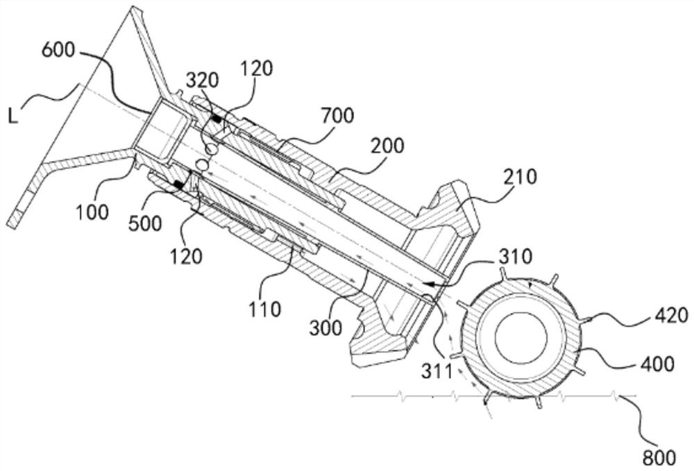
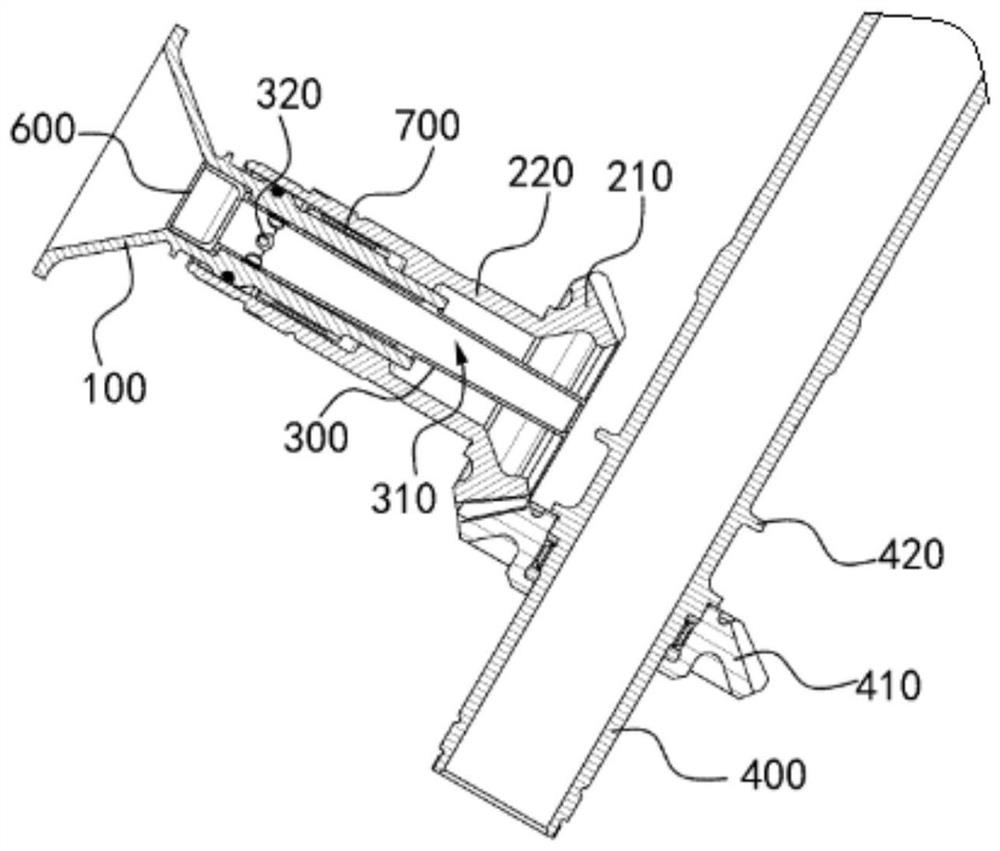
[0048] Such as figure 2 and image 3 as shown, figure 2 is a schematic diagram of a lubrication structure of a transmission mechanism shown according to an exemplary embodiment. image 3 It is a schematic diagram of another perspective of the lubricating structure of the transmission mechanism shown according to an exemplary embodiment. In an exemplary embodiment, the transmission mechanism includes an input shaft 100 , an output shaft 200 and a rotating shaft 400 , the input shaft 100 is linked to the output shaft 200 , and the output shaft 200 is linked to the rotating shaft 400 .

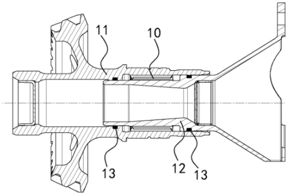
[0049] Such as figure 2 and image 3As shown, in some embodiments, both the input shaft 100 and the output shaft 200 are hollow structures, and the output shaft 200 is sleeved outside the input shaft 100, between the inner side wall of the output shaft 200 and the outer side wall of the input shaft 100 A keyed connection, such as a spline pair 700 , is formed to transmit power from the in...

Embodiment 2

[0060] In some embodiments, the in-out relationship of the input and output shafts can be reversed. Specifically, the input shaft can be sheathed outside the output shaft, and the rotating shaft can be linked to the input shaft or the output shaft. The oil collecting tube is fixedly connected to the inside of the output shaft, and other structures and beneficial effects are basically the same as those of the first embodiment above, and will not be repeated here.

Embodiment 3

[0062] An embodiment of the present invention provides a lubrication structure for a transmission mechanism. The transmission mechanism of this embodiment includes an input shaft, an output shaft and a rotating shaft. The output shaft is sleeved outside the input shaft, and the input shaft and the output shaft are connected by a key. , the rotating shaft is linked to the input shaft or output shaft. The structures and connections of the input shaft, the output shaft and the rotating shaft are basically the same as those of the first and second embodiments above, and will not be repeated here. The difference between embodiment three and above embodiment one and embodiment two is:

[0063] The lubricating structure of this embodiment includes an oil inlet channel, an oil return channel, and a plurality of first oil holes. The oil inlet channel is formed inside the input shaft and runs through the end face of the input shaft, so that the oil is thrown off by the oil rejection str...


PUM


Abstract

The invention provides a lubricating structure for a transmission mechanism. The transmission mechanism includes an inner transmission shaft, an outer transmission shaft and a rotating shaft sheathed on the outside of the inner transmission shaft. The inner transmission shaft and the outer transmission shaft are connected by a key, and the rotating shaft Linked to the inner drive shaft or the outer drive shaft; the lubricating structure includes an oil collecting tube, an oil return flow channel, a first oil hole and a second oil hole, the oil collecting tube is set in the inner drive shaft and has an oil inlet flow channel, and the oil inlet The oil passage has an inner conical surface; the oil return passage is set between the inner transmission shaft and the outer transmission shaft, and the key is located on the path of the oil return passage; the first oil hole is arranged on the inner transmission shaft and communicated with the oil return flow channel; the second oil hole is set on the oil collecting tube and connected to the oil inlet channel, an oil collecting groove is formed between the outer wall of the oil collecting tube and the inner side wall of the inner transmission shaft, and the oil collecting grooves are respectively connected to the first oil hole and the second oil hole; the outside of the rotating shaft is provided with an oil throwing structure, and the oil throwing structure can throw the lubricating oil in the oil pool into the oil flow channel.

Description

technical field [0001] The present invention generally relates to the technical field of lubrication, and specifically relates to a lubrication structure of a transmission mechanism. Background technique [0002] Helicopter tail reducers generally use the "splash lubrication" method to achieve lubrication and cooling, that is, during the high-speed rotation of the gear, the gear teeth throw the lubricating oil in the oil pool to the inner cavity wall of the casing, and the oil collecting pocket on the inner cavity wall of the casing After the lubricating oil is collected, the lubricating oil is transported along the oil passage on the casing wall to each component that needs lubrication and cooling. However, for those areas located inside the components, since this area is far away from the casing wall, and it is difficult to connect with the oil circuit on the casing wall, this area cannot be lubricated and cooled. [0003] In order to solve the above problems, the prior a...

Claims


Application Information

Patent Timeline
Patent Type & Authority Patents(China)
IPC IPC(8): F16H57/04B08B15/04
CPCB08B15/04F16H57/043F16H57/0434
Inventor 阳新元陈金张川苏新生
Owner AECC HUNAN AVIATION POWERPLANT RES INST
Why Eureka
Try Eureka