Heat exchanging fin group, heat exchanger and air conditioner

A technology of heat exchange fins and fins, which is applied in the field of heat exchangers, can solve the problems of reducing the heat exchange efficiency of the rear fins, and achieve the effects of avoiding processing difficulties, preventing a large reduction, and improving the heat exchange efficiency.

Pending Publication Date: 2020-08-07
GREE ELECTRIC APPLIANCES INC OF ZHUHAI
View PDF0 Cites 1 Cited by
  • Summary
  • Abstract
  • Description
  • Claims
  • Application Information

AI Technical Summary

Problems solved by technology

[0004] Therefore, the technical problem to be solved by the present invention is to overcome the defect in the prior art that there is a heat-affected zone between the double or mult

Method used


Image

  • Heat exchanging fin group, heat exchanger and air conditioner
  • Heat exchanging fin group, heat exchanger and air conditioner
  • Heat exchanging fin group, heat exchanger and air conditioner

Examples


Example Embodiment

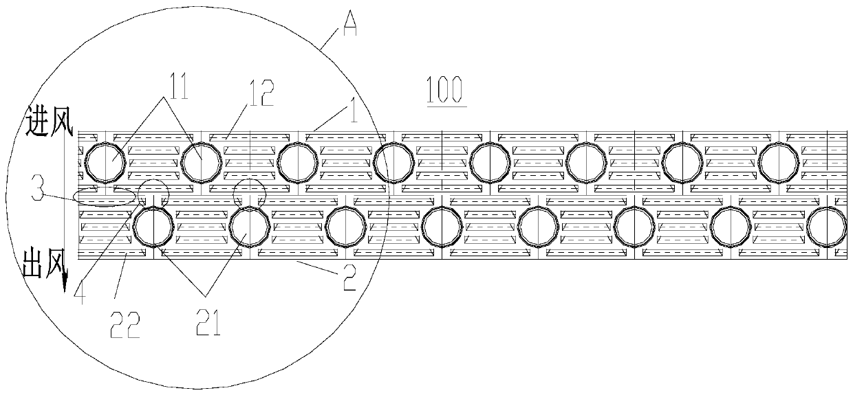
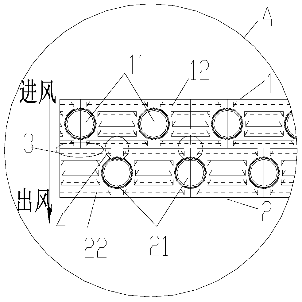
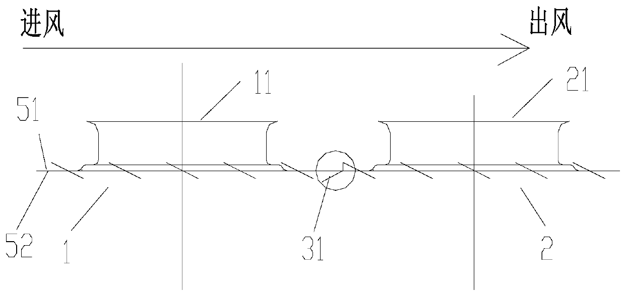
[0024] Such as Figure 1-4 As shown, the present invention provides a heat exchange fin group, which includes:

[0025] The first row of fins 1 and the second row of fins 2, the first row of fins 1 and the second row of fins 2 are arranged in sequence along the airflow direction, and the second row of fins 2 are arranged on the The first row of fins 1 is provided with at least one first pipe hole 11 through which the heat exchange tube passes along the airflow direction, and the second row of fins 2 is provided with There is at least one second tube hole 21 that can accommodate the heat exchange tube. The second tube hole 21 is opposite to the position between the two adjacent first tube holes 11 along the direction of air flow, and extends along The structure between the first row of fins 1 and the second row of fins 2 that is opposite to the first tube hole 11 in the direction of airflow is a structure with a gap 3 (the gap here is disconnected) The structure includes a struc...


PUM


Abstract

The invention provides a heat exchanging fin group, a heat exchanger and an air conditioner. The heat exchanging fin group comprises a first row of fins and a second row of fins; the first row of finsand the second row of fins are sequentially arranged in the airflow flow direction; first pipe holes are formed in the first row of fins; second pipe holes are formed in the second row of fins; in the airflow flow direction, the second pipe holes and the two adjacent first pipe holes are opposite in position; structures in the airflow flow direction, opposite to the first pipe holes and between the first row of fins and the second row of fins are disconnected at an interval; and structures in the airflow flow direction, opposite to the second pipe holes and between the first row of fins and the second row of fins are connected. The heat exchanging fin group can cut off the heat effect of the first row of fins on the maximum area of the second row of fins, so that the influence of the downstream row of fins to the upstream row of fins is smaller, and the situation that the heat exchanging efficiency of the rear row of fins is greatly reduced due to the heat effect can be effectively prevented.

Description

technical field [0001] The invention relates to the technical field of heat exchangers, in particular to a heat exchange fin group, a heat exchanger and an air conditioner. Background technique [0002] The fins of the air conditioner internal unit are mainly double-row structure, such as figure 1 As shown, the fins of the two-row structure are connected as a whole. This structural feature will cause the copper tubes and fins in the air inlet section to perform heat exchange first during the process from the air inlet to the air outlet. Since the two rows of fins are connected As a whole, there will be heat conduction and heat transfer between the two, and the heat-affected zone will affect the heat exchange of the fins in the rear section, resulting in a significant decrease in the heat exchange efficiency between the fins in the rear row and the airflow. [0003] Due to the heat-affected zone between the double or multiple rows of fins in the prior art, the heat transfer ...

Claims


Application Information

Patent Timeline
IPC IPC(8): F28F1/32F24F1/0067
CPCF24F1/0067F28F1/32
Inventor 黄起建王公文倪雪辉朱栋琦
Owner GREE ELECTRIC APPLIANCES INC OF ZHUHAI
Why Eureka
Try Eureka