An electric heating carburetor

A technology of electric heating and carburizing oil, which is applied in lighting and heating equipment, water heaters, chemical industry, etc. It can solve the problems of easy gelatinization and carbonization of electric heating rods, pollution of the environment by smoke, and pollution of raw materials by carbonized particles, so as to avoid heat exchange efficiency problems, ensure product quality, and avoid the effect of heating and gelatinization

Active Publication Date: 2019-03-26
LANGFANG AIDI IND CONTROL TECH CO LTD
View PDF5 Cites 0 Cited by
  • Summary
  • Abstract
  • Description
  • Claims
  • Application Information

AI Technical Summary

Problems solved by technology

Due to the existence of external equipment, there are problems of heat exchange efficiency, pipeline heat loss, and high production environment temperature; due to the existence of circulating pump valve equipment, heat exchange equipment, boilers, and circulating pipeline equipment, there must be high maintenance costs. problems; and if there is heat medium in these devices, there will be leakage, which will pollute the environment, pollute raw materials, and easily cause quality and safety accidents
Existing carburetion equipment uses hot water, steam, and heat transfer oil as three heat sources, as well as electric heating carburetion equipment that uses electric heating rods to heat. However, electric heating rods cannot directly contact raw materials. The phenomenon of gelatinization and carbonization, especially in the carburetion process, although the oil can also melt, but the electric heating rod is very easy to gelatinize and carbonize, and even smoke, carbonized particles pollute raw materials, smoke pollutes the environment, and even has flammable and explosion-proof problems

Method used


Image

  • An electric heating carburetor
  • An electric heating carburetor
  • An electric heating carburetor

Examples


Embodiment Construction

[0018] The technical solution of this patent will be further described in detail below in conjunction with specific embodiments.

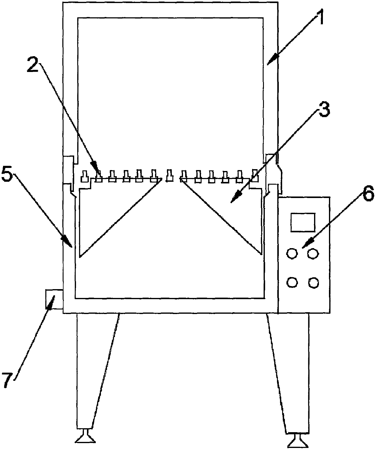
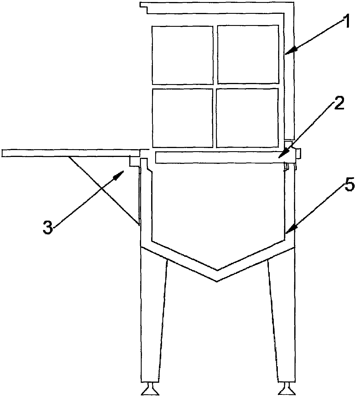
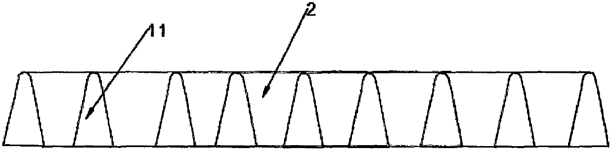
[0019] see Figure 1-5 , a kind of electric heating oil equipment, comprising electric heating insulation storage tank 5, electric heating oil grate 2, heat preservation upper cover 1, folding support frame flip platform door 3, heating unit structure 11 and control box 6, said electric heating oil grate 2 Installed on the upper part of the electric thermal insulation storage tank 5, the thermal insulation upper cover 1 is installed on the upper part of the electric heating oil grate 2, the control box 6 is located on one side of the electric thermal insulation storage tank 5, and the electric heating oil grate 2 is assembled and welded by multiple heating unit structures 11 in parallel The folding support frame flips the platform door 3 and is installed on the upper edge of the front end of the electric thermal insulation storage tank 5. The heati...


PUM


Abstract

The invention discloses electric heating oil melting equipment. The electric heating oil melting equipment comprises an electric heating heat preservation storage tank, an electric heating oil melting comb, an upper heat preservation cover, a folding supporting frame overturning platform door, a heating unit structure and a control box. The electric heating oil melting equipment can replace heating equipment which takes hot water, steam and heat conducting oil as heating media, so that the investment on heat exchange pump valve equipment, a boiler and circulation heat supply pipeline equipment is reduced; the problem about heat exchange efficiency caused by the existence of external heating circulating equipment, the problem about pipeline heat loss and the problem of over-high production environment temperature are avoided; the problem that quality safety accidents are prone to happening because of leakage, environment pollution and raw material pollution due to the existence of the heating media in conventional equipment is avoided; the problems of gelatinization, carbonization, smoking and over-temperature caused by the heating of an electric heating rod are avoided; the electric heating oil melting equipment is energy-saving and consumption-reducing, and can ensure the product quality better; particularly, more attention is given to the characteristics of leakage free and safety of the electric heating oil melting equipment during the production processes of heating, melting and transporting of food, medicines and chemical industry.

Description

technical field [0001] The invention relates to a food and chemical melting device, in particular to an electric heating oil melting device. Background technique [0002] The carburetor is a melting device commonly used in food and chemical production. Currently, the carburetor commonly used in the market generally adopts the heating structure of hot water, steam and heat transfer oil. These three heating methods require external Heating equipment such as: heat exchange pump valve equipment, boilers, circulating heating pipeline equipment. Due to the existence of external equipment, there are problems of heat exchange efficiency, pipeline heat loss, and high production environment temperature; due to the existence of circulating pump valve equipment, heat exchange equipment, boilers, and circulating pipeline equipment, there must be high maintenance costs. problems; and if there is heat medium in these devices, there will be leakage, which will pollute the environment, poll...

Claims


Application Information

Patent Timeline
Patent Type & Authority Patents(China)
IPC IPC(8): F24H1/20F24H9/18F24H9/20
CPCF24H1/202F24H9/1827F24H9/2021F24H2250/02F24H2250/04Y02P20/10
Inventor 赵亚青
Owner LANGFANG AIDI IND CONTROL TECH CO LTD
Why Eureka
Try Eureka