Integral heat exchanger

a heat exchanger and integrated technology, applied in indirect heat exchangers, machines/engines, lighting and heating apparatus, etc., can solve the problems of reducing the charging efficiency of the cylinder, affecting and generating a large amount of heat in the internal combustion engine. , to achieve the effect of enhancing the heat exchange efficiency of the second heat exchange medium

Inactive Publication Date: 2018-11-08
HANON SYST
View PDF0 Cites 0 Cited by
  • Summary
  • Abstract
  • Description
  • Claims
  • Application Information

AI Technical Summary

Benefits of technology

[0019]According to the present invention, preferably, the internal sectional area of each second pipe is smaller than that of each first pipe, so that the second pipes are located on a portion in which the second heat exchange medium is collectively introduced, thus preventing the heat exchange efficiency from being decreased due to the collection of the second heat exchange medium to the specific pipes of the heat exchange member.
[0021]According to the present invention, preferably, the heat exchange member has a spiral protrusion formed along the outer peripheral surface thereof, thus increasing the contact area with the first heat exchange medium, guiding the movement of the first heat exchange medium, and enhancing the performance of the heat exchange between the first heat exchange medium and the second heat exchange medium.
[0023]According to the present invention, preferably, the integral heat exchanger further includes a distribution member located inside the second inlet portion so as to evenly distribute the second heat exchange medium to the heat exchange member.
[0033]According to the present invention, preferably, the second space portion and the fourth space portion are formed at the lower side of the integral heat exchange in a direction of a height of a vehicle, so that an amount of vehicle wind introduced is relatively large to enhance the heat exchange efficiency of the second heat exchange medium.

Problems solved by technology

Generally, an internal combustion engine always generates a large amount of heat during high temperature and high pressure gas is burnt, and if the heat is not cooled appropriately, various parts like cylinders and pistons may be damaged due to the overheating of the engine.
However, the rapidly compressed air through the charger is very raised in temperature so that it has an expanded volume and a low degree of oxygen concentration, thus causing the charging efficiency in the cylinder to be decreased.
On the other hand, the water-cooled intercooler has the similar operating principle to the air-cooled intercooler 10′, and when internal charge air is cooled, the water-cooled intercooler uses cooling water or water of the vehicle, instead of the external air, so that the cooling efficiency is excellent, but the intercooler structure is complicated, thus making it difficult in installation and maintenance.
Like this, the cooling system having the water-cooled intercooler 10 includes a large number of parts, so that the structure of the system becomes complicated, and further, there is a limit in the temperature cooled only with the heat exchange with the cooling water, so that the heat exchange efficiency of the system may be decreased.

Method used


Image

  • Integral heat exchanger
  • Integral heat exchanger
  • Integral heat exchanger

Examples


Embodiment Construction

[0091]Hereinafter, an explanation on an integral heat exchanger according to the present invention will be in detail given with reference to the attached drawing.

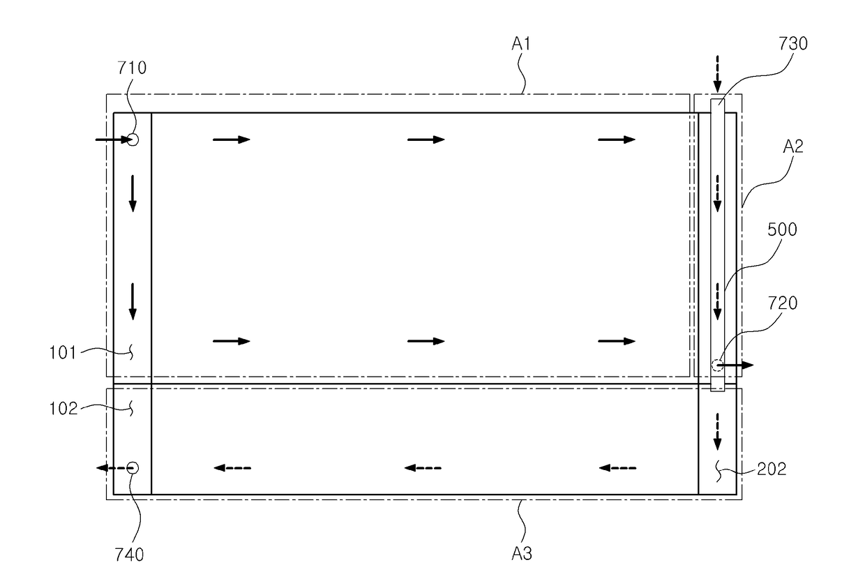
[0092]FIG. 3 is a schematic view showing an integral heat exchanger 1000 according to a first embodiment of the present invention. The integral heat exchanger 1000 according to the first embodiment of the present invention includes: a first heat exchange portion A1 for performing the heat exchange of a first heat exchange medium with external air; a second heat exchange portion A2 separated from the first heat exchange portion A1 and performing the heat exchange of a second heat exchange medium with the first heat exchange medium; and a third heat exchange portion A3 for introducing the second heat exchange medium passing through the second heat exchange portion A2 thereinto and performing the heat exchange of the second heat exchange medium with external air, wherein the first to third heat exchange portions A1 to A3 are f...


PUM


Abstract

The present invention relates to an integral heat exchanger including: a first heat exchange portion for performing the heat exchange of a first heat exchange medium with external air; a second heat exchange portion separated from the first heat exchange portion and performing the heat exchange of a second heat exchange medium with the first heat exchange medium; and a third heat exchange portion for introducing the second heat exchange medium passing through the second heat exchange portion and to perform the heat exchange of the introduced second heat exchange medium with external air, wherein the first to third heat exchange portions are formed in one body integrally to each other.

Description

CROSS-REFERENCE TO RELATED APPLICATIONS[0001]This patent application is a divisional patent application of U.S. patent application Ser. No. 14 / 907,011, which is a United States national phase patent application based on PCT patent application number PCT / KR2015 / 004199 filed Apr. 28, 2015, which claims the benefit of Korean Patent Application Nos. 10-2014-0089938 dated Jul. 16, 2014, 10-2015-0001422 dated Jan. 6, 2015, 10-2015-0001228 dated Jan. 6, 2015, and 10-2015-0001229 dated Jan. 6, 2015. The disclosures of the above patent applications are hereby incorporated herein by reference in their entirety.FIELD OF THE INVENTION[0002]The present invention relates to an integral heat exchanger, and more particularly, to an integral heat exchanger that conducts the heat exchange of a first heat exchange medium in an air-cooled manner and conducts the heat exchange of a second heat exchange medium in a water-cooled and air-cooled manner.BACKGROUND OF THE RELATED ART[0003]A radiator and an in...

Claims


Application Information

Patent Timeline
Patent Type & Authority Applications(United States)
IPC IPC(8): F28D1/04F28F9/02F28F1/36
CPCF28F9/0265F28F9/0212F28F1/36F28D1/0443Y02T10/146F28F9/0234F28D2021/0082F28F1/126F28F1/06F28D1/05391F28D1/0461F02B29/0412Y02T10/12
Inventor JO, A-RACHUN, TAE-SOOKIM, TAEK-KEUNLEE, YANG-WOO
Owner HANON SYST
Why Eureka
Try Eureka