Heat exchanger for air compressor

Inactive Publication Date: 2005-04-21
HITACHI PLANT TECH LTD
View PDF8 Cites 1 Cited by
  • Summary
  • Abstract
  • Description
  • Claims
  • Application Information

AI Technical Summary

Benefits of technology

[0006] In view of disadvantages of the above prior art, an object of the present invention is to prevent the heat exchange efficiency from decreasing due to the leakage between a cooling apparatus nest and a casing,

Problems solved by technology

The sealing ability is improved by way of each sealing method described in the above prior art, however, it becomes complicated to process the seal part because of its complicated structur

Method used


Image

  • Heat exchanger for air compressor
  • Heat exchanger for air compressor
  • Heat exchanger for air compressor

Examples


Example

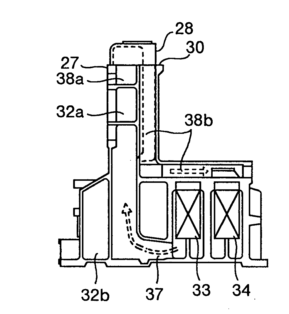
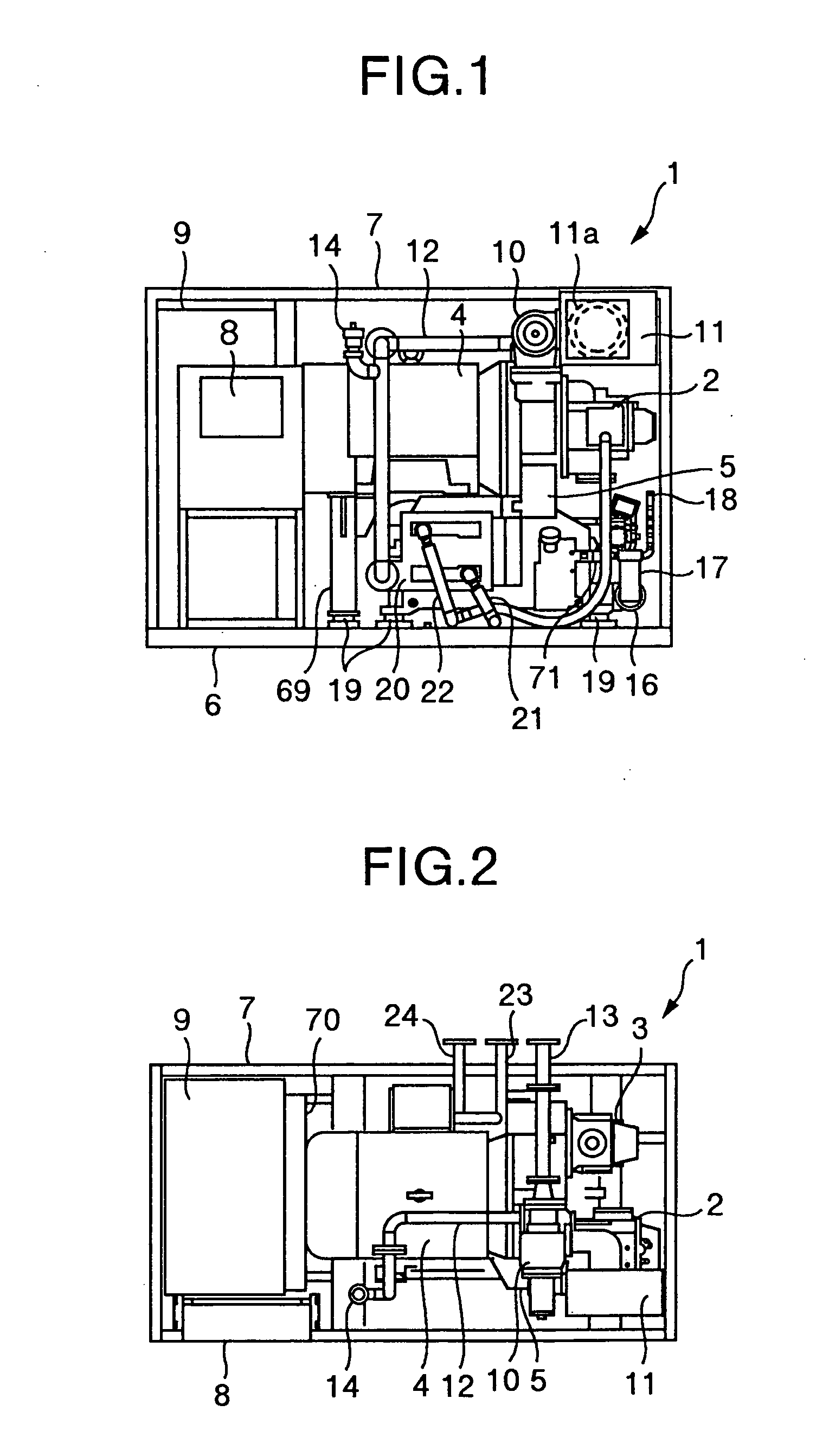
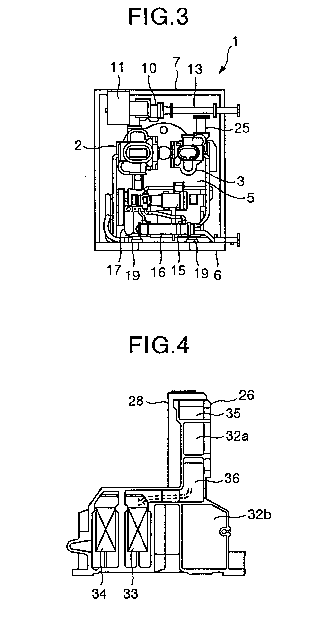
[0023] Now, some embodiments of the present invention will be described referring to the drawings. At first, findings based on preliminary tests related to the present invention will be described. In a heat exchanger according to the present invention, there are formed flow passages which are separated by a partition plate and orthogonal to each other, through which two different kinds of working fluids flow respectively. When the working fluids flow through the orthogonal flow passages respectively, the heat is transferred from a high temperature chamber on a high temperature side to a low temperature chamber on a low temperature side through the partition plate. This allows the fluid on the high temperature side to be cooled. The high temperature chamber and the low temperature chamber make a pair, and a plurality of pairs are stacked in multiple layers to form a heat exchanger, referred to as a nest. Examples of such heat exchangers are described in Heat Transfer Engineering Data...


PUM


Abstract

A heat exchanger used in a screw air compressor has a low temperature chamber through which low temperature fluid flows and a high temperature chamber through which high temperature fluid flows. The low temperature chamber and the high temperature chamber are separated by a partition plate. The high temperature chambers and the low temperature chambers are alternately arranged in layers, so that the low temperature chambers are disposed at both ends in a layered direction. Additionally, the flowing direction of the low temperature fluid in the low temperature chambers and the flowing direction of the high temperature fluid in the high temperature chambers are substantially orthogonal to each other.

Description

CROSS REFERENCE TO RELATED APPLICATION [0001] This application is a divisional application of U.S. Ser. No. 09 / 921,926, filed Aug. 6, 2001, the contents of which are incorporated hereby by reference.BACKGROUND OF THE INVENTION [0002] The present invention relates to a medium or small capacity air compressor which is used as a power air source or the like for factories, and more particularly to a heat exchanger provided in those air compressors. [0003] A screw-type compressor and a compact turbo compressor are known as a medium or small capacity air compressor whose discharge pressure is approximately 0.7 MPa in gauge pressure and whose output power is in a class from less than 100 kW to several hundreds kW, and are used as a power air source for factories. An example of such an air compressor is disclosed in JP-A-8-105386 or JP-A-2000-120585. In these specifications, a laminated type of heat exchanger or a fin tube type of heat exchanger is used for cooling compressed air generated ...

Claims


Application Information

Patent Timeline
IPC IPC(8): F28D9/00F28F3/02F28F9/00
CPCF28D9/0062F28F9/00F28F3/025F28F2250/102F28D9/00
Inventor MIURA, HARUOTAKAHASHI, KAZUKITSURU, SEIJITANIYAMA, MINORUNARUSE, TOMOHIROHATTORI, TOSHIO
Owner HITACHI PLANT TECH LTD
Why Eureka
Try Eureka