Key mechanism and electronic equipment

A technology of buttons and keycaps, which is applied in the direction of circuits, electric switches, electrical components, etc., can solve problems such as inability to synchronize actions, the height of buttons cannot meet the design requirements of light and thin equipment, and poor coordination, so as to improve the use of tactile effects

Active Publication Date: 2020-08-07
HEFEI LCFC INFORMATION TECH
View PDF8 Cites 1 Cited by
  • Summary
  • Abstract
  • Description
  • Claims
  • Application Information

AI Technical Summary

Problems solved by technology

[0002] At present, many electronic devices, such as notebook computers, tend to be light and thin. However, in the prior art, the keyboard has a greater impact on the thickness of the device. Because the structure of each key on the keyboard has certain disadvantages, and the keycap and user Due to the poor coordination between the mechanisms that drive the keycap up and down, the two cannot operate synchronously, so the current key height cannot meet the thin and light design requirements of the device

Method used


Image

  • Key mechanism and electronic equipment
  • Key mechanism and electronic equipment
  • Key mechanism and electronic equipment

Examples


Embodiment 1

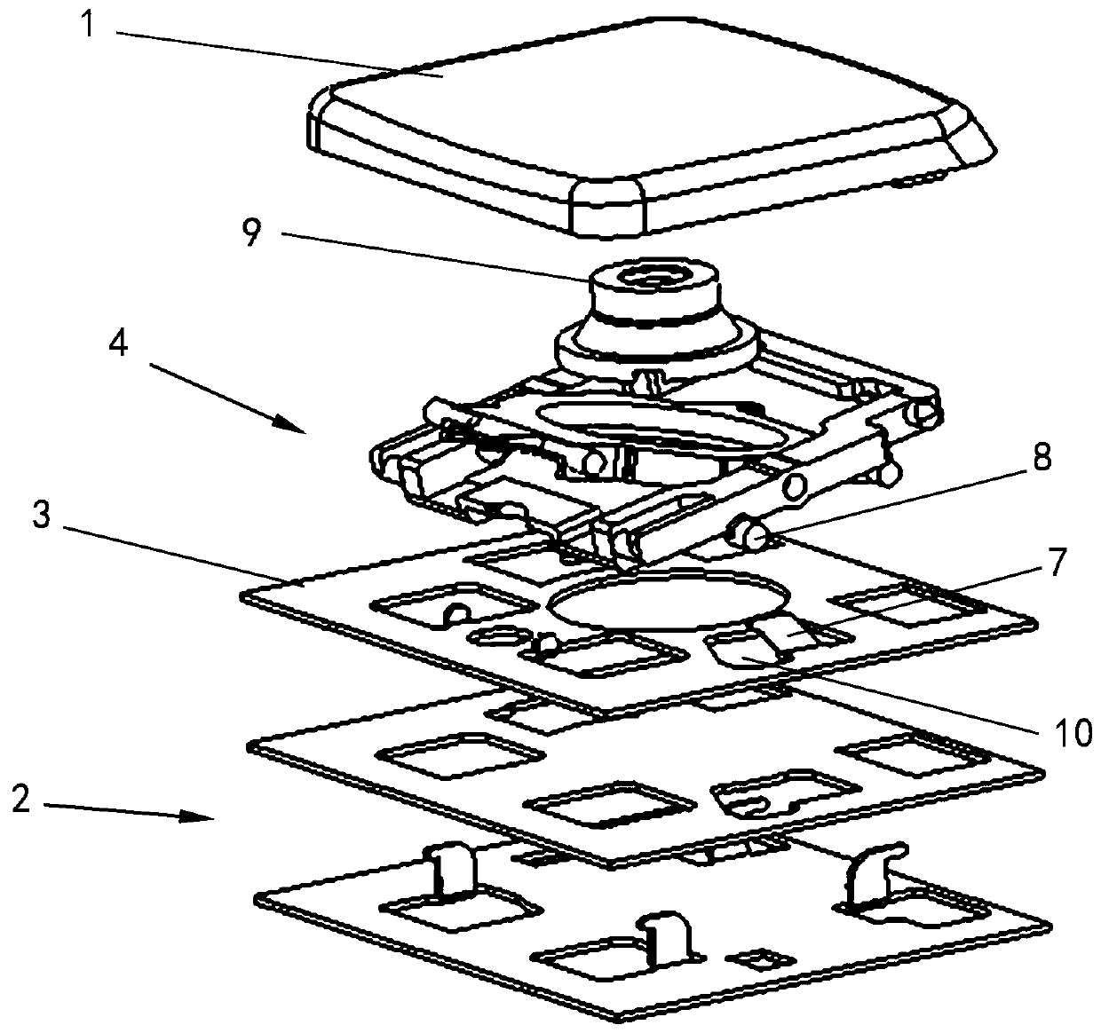
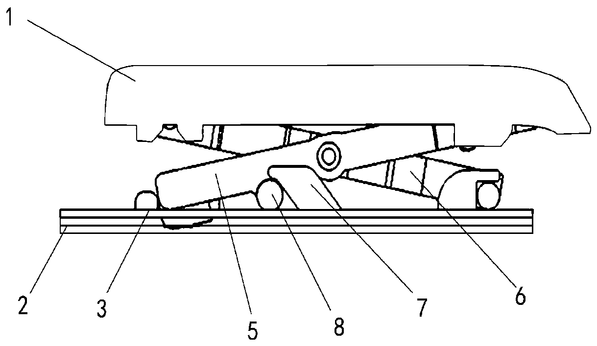
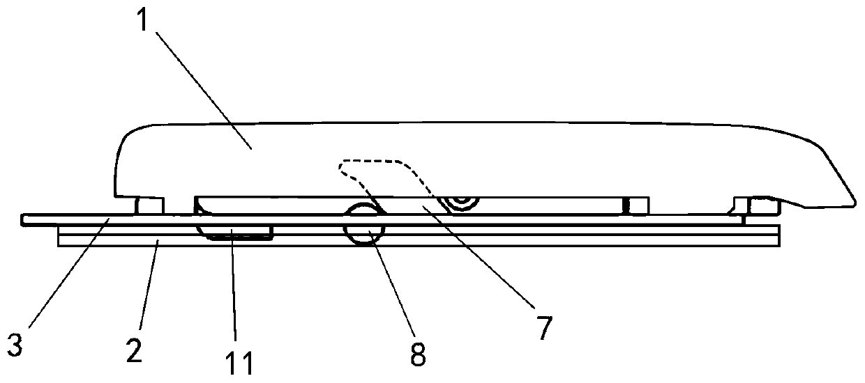
[0055] Such as figure 1 , figure 2 , image 3 , Figure 4 As shown, the first stop portion 7 in this embodiment is formed by a portion of the limiting member 3 extending obliquely toward the keycap 1 , and can specifically be an inclined baffle. The second stop portion 8 is formed by extending part of the first bracket 5 toward the first stop portion 7 , and may specifically be a protruding post, such as a cylinder. The second stopper 8 is located between the first stopper 7 and the limiting member 3, and the first stopper 7 abuts against part of the second stopper 8 at least when the keycap 1 is in the first position, so as to A force towards the conductive base 2 is exerted on the lifting bracket 4 and the keycap 1 through the second stopper portion 8 . That is, at least when the keycap 1 is in the first position, the inclined surface of the first stopper 7 toward the direction of the conductive base 2 at least presses against a part of the second stopper 8, so as to ap...

Embodiment 2

[0059] Such as Figure 5 , Figure 6 and Figure 7 As shown, the first stopper 7 in this embodiment is formed by extending part of the stopper 3 toward the direction close to the keycap 1, the first stopper 7 has a bending area, specifically as Figure 5 , Figure 6 As shown in , it is approximately in the shape of "7", wherein the part parallel to the conductive base 2 is the bending area. The second stopper 8 is formed by extending part of the first bracket 5 toward the first stopper 7, which can be specifically shown in the figure Figure 5 , Figure 7 The oblong body shown in the figure, the end of the second stopper 8 facing the limiting member 3 is inclined towards the bending area towards the limiting member 3, and at least when the keycap 1 is in the first position, it is in line with the bending area abut against each other so that the bending area can apply a force toward the conductive base 2 to the lifting bracket 4 and the keycap 1 through the second stopper ...


PUM


Abstract

The embodiment of the invention provides a key mechanism and electronic equipment. The key mechanism comprises a key cap, a conductive base and a lifting assembly which abuts against the key cap and the conductive base, and the lifting assembly descends together in the process that the key cap is pressed from a first position to descend to a second position and accumulates restoring force so as tobe used for pushing the key cap to do ascending motion towards the first position, wherein the height, relative to the conductive base, of the first position meets a specific threshold value; the lifting assembly comprises a first stopping part and a second stopping part, the first stopping part and the second stopping part abut against each other at least when the key cap is located at the firstposition, force is applied to the lifting assembly so as to offset part of the restoring force, and it is guaranteed that when the key cap rises to the first position, the key cap stops rising continuously. The key mechanism provided by the embodiment of the invention can effectively control the height of the key, and supports the light and thin design of the electronic equipment.

Description

technical field [0001] Embodiments of the present invention relate to the field of smart devices, and in particular to a key mechanism and electronic devices. Background technique [0002] At present, many electronic devices, such as notebook computers, tend to be light and thin. However, in the prior art, the keyboard has a greater impact on the thickness of the device. Because the structure of each key on the keyboard has certain disadvantages, and the keycap and user Due to the poor coordination between the mechanisms that drive the keycaps up and down, the two cannot operate synchronously, so the current key height cannot meet the thin and light design requirements of the device. Contents of the invention [0003] The embodiment of the present invention provides a key mechanism capable of effectively controlling the key height, and an electronic device having the key mechanism. [0004] In order to solve the above technical problems, an embodiment of the present inven...

Claims


Application Information

Patent Timeline
Patent Type & Authority Applications(China)
IPC IPC(8): H01H13/7073H01H33/666
CPCH01H13/7073H01H33/666
Inventor 萧宏宇张锦祥陈易圣高光正
Owner HEFEI LCFC INFORMATION TECH
Why Eureka
Try Eureka