Connector

A connector and transfer technology, applied in the direction of connection, connecting device parts, electrical components, etc., can solve the problems of small floating amount of the connector, inability to realize large tolerance connection, etc., and achieve small floating interval and large tolerance. Connect and ensure the effect of the installation position

Active Publication Date: 2020-08-07
CHINA AVIATION OPTICAL-ELECTRICAL TECH CO LTD
View PDF6 Cites 2 Cited by
  • Summary
  • Abstract
  • Description
  • Claims
  • Application Information

AI Technical Summary

Problems solved by technology

[0004] The purpose of the present invention is to provide a connector to solve the problem that the existing connector has a small floating amount and cannot realize a large tolerance connection

Method used


Image

  • Connector
  • Connector
  • Connector

Examples


Embodiment 1

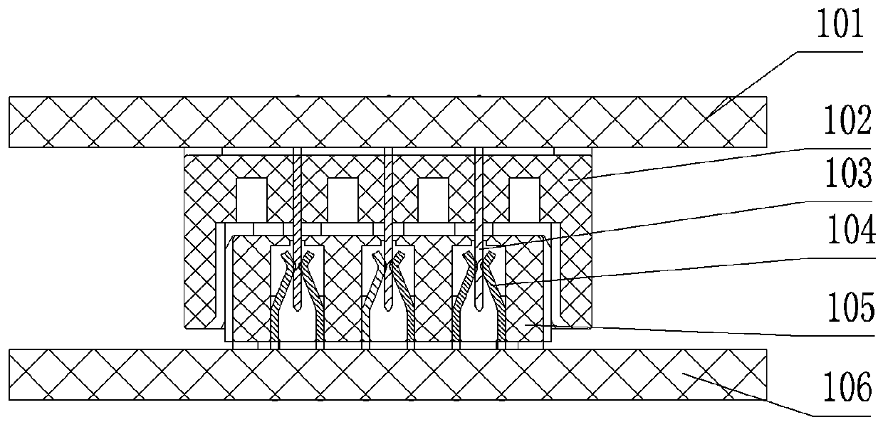
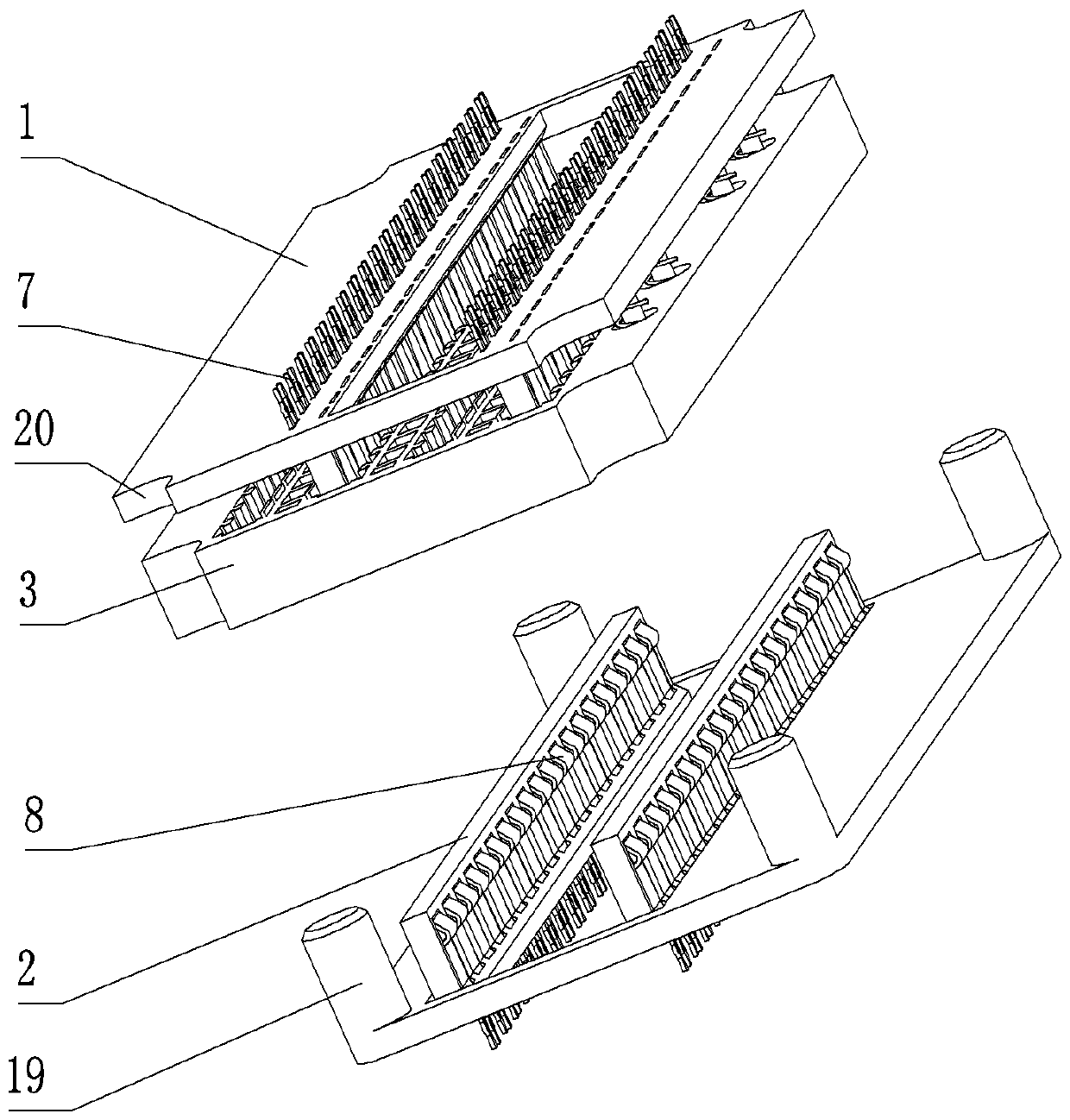
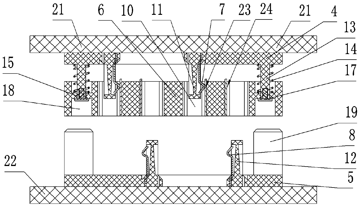
[0048] Such as figure 2 and image 3 As shown, the connector includes a first plug-in module 1, a second plug-in module 2 and an adapter module 3, the first printed board 21 is connected to the first plug-in module 1, and the second printed board 22 is connected to the second pair of plug-in modules. plug-in module connection. The adapter module 3 is arranged between the first plug-in module 1 and the second plug-in module 2 , and the first plug-in module 1 and the second plug-in module 2 are plugged on the adapter module 3 . The first plug-in module 1 and the adapter module 3 are provided with an arc-shaped guide groove 20, and the second plug-in module 2 is provided with an adapter guide column 19, and the adapter guide column 19 guides and cooperates with the arc-shaped guide groove 20, so as to Guaranteed installation location.

[0049] In order to illustrate this embodiment more clearly, with image 3 The up and down direction of the connector assembly is the up and ...

Embodiment 2

[0065] Embodiment 2 of the connector in the present invention, the difference between this embodiment and Embodiment 1 is that the stop position in Embodiment 1 is formed by the plug-in end face of the second plug-in module, and in this embodiment, A partial protrusion is provided on the second plug-in end surface, and the partial protrusion is used to form a stop position.

Embodiment 3

[0066] Embodiment 3 of the connector in the present invention, the difference between this embodiment and Embodiment 1 is that the first contact and the second contact in Embodiment 1 are spring-type structures, and the transfer contact is U-shaped. structure, but in this embodiment, the first contact and the second contact are pin-type structures, and the transfer contacts are reed-type structures.


PUM


Abstract

The invention relates to a connector, which comprises a first plug-in module, a second plug-in module and a switching module, wherein the first plug-in module is provided with a first contact element,the second plug-in module is provided with a second contact element, and the switching module is provided with a switching contact element; the switching module is arranged on the first plug-in module in a guiding manner, and a reset spring is arranged between the switching module and the first plug-in module, so that the switching module can extend forwards relative to the first plug-in module;the first contact element and the second contact element are in sliding contact with the switching contact element; the second plug-in module is provided with a stop part, so that the switching modulecan retreat relative to the first plug-in module. Compared with a connector without a switching module in the prior art, the second contact element can be contacted with the switching contact elementearlier, so that a larger floating interval can be formed between the first plug-in module and the second plug-in module, the floating amount of the connector is increased, and large-tolerance connection is realized.

Description

technical field [0001] The invention relates to a connector. Background technique [0002] The floating of the existing connector in the insertion direction is mainly ensured by the length of the overlapped portion of the two oppositely inserted contacts. Such as figure 1 The shown connector includes a first mating module 102 and a second mating module 105 that are relatively plugged in. The first mating module 102 is connected to the first printed board 101, and the second mating module 105 is connected to the second printed board. plate 106, pins 103 are provided on the first mating module 102, spring claws 104 are provided on the second mating module 105, and the pins 103 and spring claws 104 are plugged and connected. The first mating module 102 is relatively to the second The plug-in module 105 floats up and down, and the pin 103 starts to float when it comes into contact with the claw 104 . The maximum floating range depends on the maximum length of the pin 103 inser...

Claims


Application Information

Patent Timeline
Patent Type & Authority Applications(China)
IPC IPC(8): H01R12/71H01R12/91H01R13/502H01R13/627H01R13/629
CPCH01R12/71H01R12/91H01R13/502H01R13/627H01R13/629
Inventor 李立新刘向阳邹宏飞韩云钊武学顺
Owner CHINA AVIATION OPTICAL-ELECTRICAL TECH CO LTD
Why Eureka
Try Eureka