Door frame structure and disinfection cabinet provided with door frame structure

A technology for sterilizing cabinets and door frames, which is used in disinfection, window/door frames, door leaves, etc., and can solve the problems of broken control panel glass, decreased experience, and inability to solve the problem of matching the control panel glass with the door frame.

Pending Publication Date: 2020-08-11
QINGDAO HAIER WISDOM KITCHEN APPLIANCE CO LTD +1
View PDF2 Cites 0 Cited by
  • Summary
  • Abstract
  • Description
  • Claims
  • Application Information

AI Technical Summary

Problems solved by technology

[0005] Although the above-mentioned prior art proposes a technical solution for the frame of the disinfection cabinet on the door body, it cannot solve the problem of cooperation between the control panel glass and the door body frame during use, and cannot prevent the control panel glass from being in use. broken
[0006] Therefore, it is necessary to improve the deficiencies and defects of the prior art, provide a door frame structure and a disinfection cabinet equipped with the door frame structure, by setting the support structure on the control panel glass, omit The protrusion, under the action of the supporting structure, realizes the reservation of the gap between the control panel glass and the door body frame, and through the cooperation of the support structure and the door body frame, realizes the fixing of the control panel glass, avoiding the past bonding or welding In the long-term use, the problem of loosening of the control panel glass caused by glue or welding failure; at the same time, it also prevents the light emitted by the display unit in the gap from leaking from both sides of the control panel glass, resulting in a decrease in user experience

Method used


Image

  • Door frame structure and disinfection cabinet provided with door frame structure
  • Door frame structure and disinfection cabinet provided with door frame structure
  • Door frame structure and disinfection cabinet provided with door frame structure

Examples


Embodiment 1

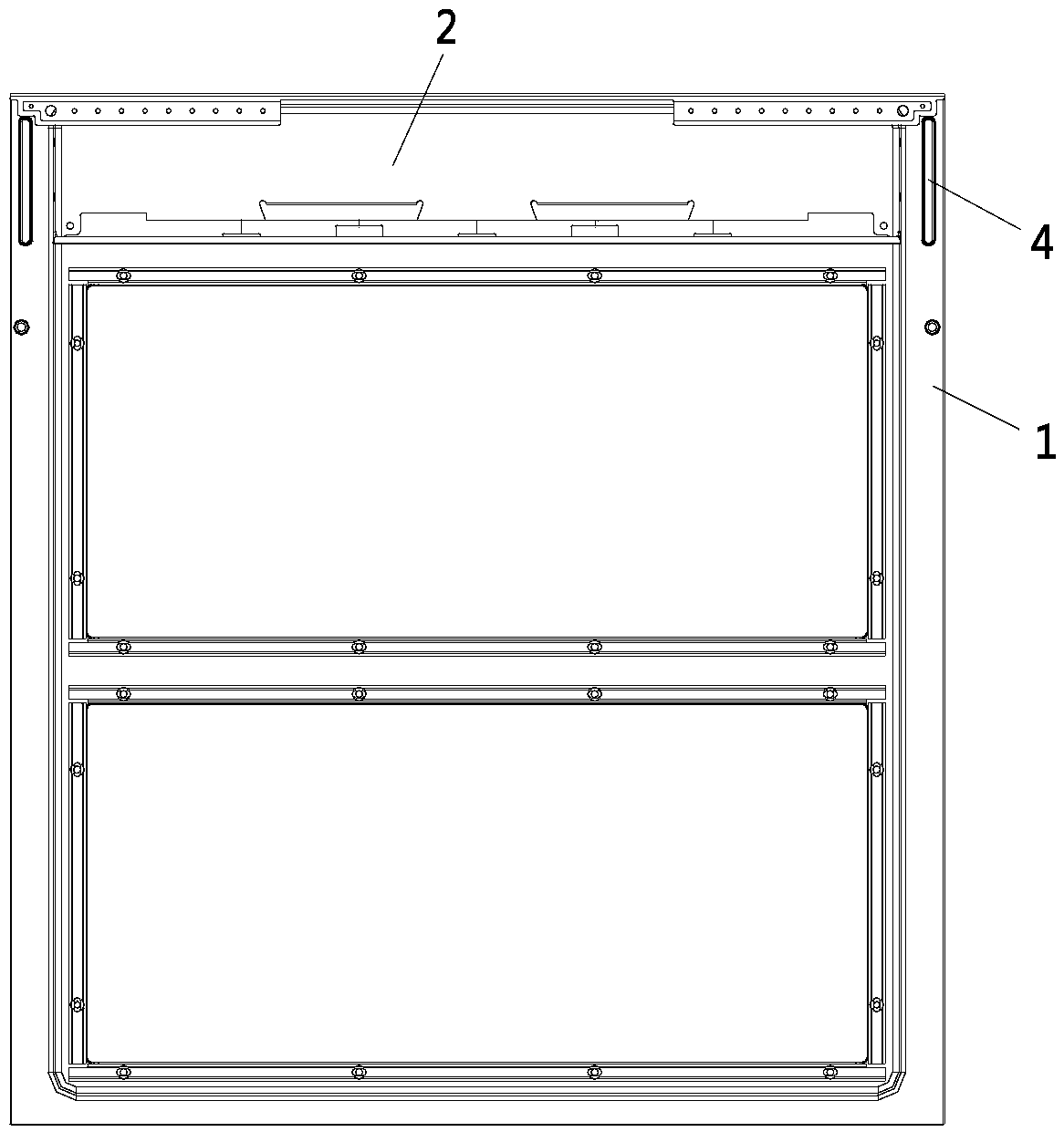
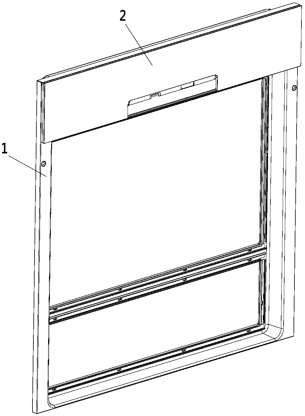
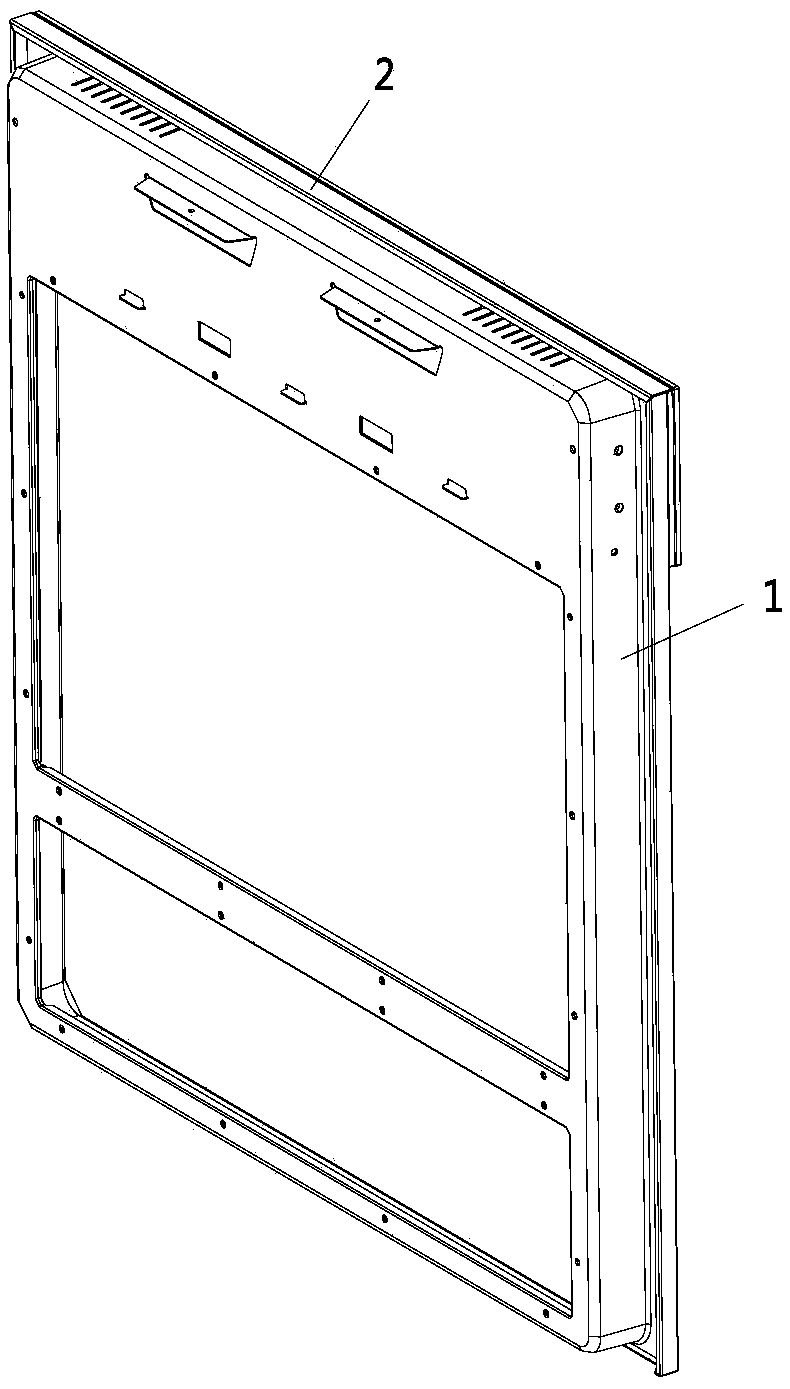
[0085] Such as Figure 2 to Figure 5 As shown, a door frame structure described in this embodiment includes a door body 1; a control panel glass 2 arranged on the door body 1; a support assembly 3 arranged between the door body 1 and the control panel glass 2 for Maintain the gap between the door body 1 and the control panel glass 2; wherein the supporting components 3 are at least arranged on both sides of the control panel glass 2, and cooperate with the frame of the door body 1 to prevent the side of the control panel glass 2 and the door body 1 from light leaks.

[0086] figure 2 It is the first schematic diagram of the door frame structure of the present invention, which mainly shows the door frame structure of the present invention and the front structure of the control panel glass 2 on the door frame structure from the perspective of the axonometric view. figure 2 It can be seen from the figure that the control panel glass 2 is set on the top of the door frame struc...

Embodiment 2

[0089] Such as Figure 2 to Figure 5 As shown, this embodiment is a further limitation of the above embodiments. The door frame structure described in this embodiment, the support assembly 3 includes a first support structure 301, a second support structure 302 and a third support structure 303; The support structure 301 is arranged on both sides of the control panel glass 2 to prevent light leakage from the sides after the control panel glass 2 cooperates with the door body 1; the second support structure 302 is arranged on the top of the control panel glass 2 to at least cover the top of the door body 1 Partial inclusion; the third support structure 303 is arranged on the inner side of the control panel glass 2 and cooperates with the frame of the door body 1 to realize the fixing of the control panel glass 2 and the door body 1 .

[0090] Figure 5 It is a structural schematic diagram of the support assembly 3 of the present invention, showing the assembly of the control p...

Embodiment 3

[0092] Such as Figure 2 to Figure 5 As shown, this embodiment is a further limitation of the above-mentioned embodiment two. A door frame structure described in this embodiment, the first support structure 301, the second support structure 302 and the third support structure 303, and the control panel The glass 2 is connected by bonding.

[0093] Figure 4 It is a schematic diagram of the assembly of the control panel glass 2 and the support assembly 3 in the door frame structure of the present invention, and shows the assembly of the control panel glass 2 and the support assembly 3 of the present invention from the perspective of the isometric view. Figure 4 It can be seen from the figure that a support assembly 3 is provided inside the control panel glass 2, and the support assembly 3 includes a first support structure 301 arranged on the side of the control panel glass 2, and a support structure 301 arranged on the top of the control panel glass 2 and matched with the to...


PUM


Abstract

The invention discloses a door frame structure and a disinfection cabinet provided with the door frame structure. The door frame structure comprises a door body, control panel glass and supporting assemblies. The control panel glass is arranged on the door body. The supporting assemblies are arranged between the door body and the control panel glass and used for keeping the clearance between the door body and the control panel glass. The supporting assemblies are at least arranged on the two sides of the control panel glass and cooperate with a frame of the door body so as to avoid light leaking of the side after the control panel glass cooperates with the door body. Each supporting assembly comprises a first supporting structure, a second supporting structure and a third supporting structure. According to the door frame structure and the disinfection cabinet provided with the door frame structure, the supporting structures are arranged on the control panel glass, protrusions originally arranged on the frame of the door body are omitted, under the action of the supporting structures, the clearance between the control panel glass and the frame of the door body is reserved, and through cooperation of the supporting structures and the frame of the door body, the problem that control panel glass loosening is brought by adhesive or welding failures in long-time use is avoided, wherein the problem is brought by previous binding or welding.

Description

technical field [0001] The invention belongs to the technical field of household appliances, and in particular relates to a door frame structure and a disinfection cabinet equipped with the door frame structure. Background technique [0002] With the development of science and technology, household appliances have become an important part of family life. With the improvement of people's living standards, the requirements for aesthetics and the rationality of product structure are increasing. Existing household appliances, especially disinfection The control panel glass of the cabinet is directly connected to the frame of the door body, and because the display unit or other electrical components need to be embedded between the control panel glass and the door body, a certain gap is often left between the control panel glass and the door body , and the usual solution for this gap is to set a protrusion integrated with the door body at the position corresponding to the door bod...

Claims


Application Information

Patent Timeline
Patent Type & Authority Applications(China)
IPC IPC(8): E06B3/70E06B1/52E06B5/00A61L2/26
CPCA61L2/26A61L2202/121E06B1/52E06B3/70E06B5/00
Inventor 贾忠宝王涛马少云
Owner QINGDAO HAIER WISDOM KITCHEN APPLIANCE CO LTD
Why Eureka
Try Eureka