Three-dimensional point cloud deformation method based on coded point driving

A technology of three-dimensional point cloud and coded points, which is applied in the field of aerial measurement, can solve the problems of not being able to complete the measurement of the entire component at the same time, point cloud data distortion, confusion, etc., and achieve the effect of solving the difficulty of real-time measurement

Active Publication Date: 2020-08-11
南京耘瞳科技有限公司
View PDF7 Cites 3 Cited by
  • Summary
  • Abstract
  • Description
  • Claims
  • Application Information

AI Technical Summary

Problems solved by technology

Most of the existing real-time measurement technologies are real-time measurement of static objects or instantaneous measurement of small objects. When large parts are deformed, part of the structure is in a state of motion. Due to the relatively large structure, use a 3D scanner to obtain a complete point cloud data It takes a certain amount of time, and the measurement of the entire part cannot be completed at the same time. At this time, the point cloud data of the moving structure acquired by the 3D scanner will be distorted and chaotic.

Method used


Image

  • Three-dimensional point cloud deformation method based on coded point driving
  • Three-dimensional point cloud deformation method based on coded point driving
  • Three-dimensional point cloud deformation method based on coded point driving

Examples


Embodiment Construction

[0045] The 3D point cloud deformation method based on coded point drive of the present invention will be further described in detail below in conjunction with the accompanying drawings and specific embodiments.

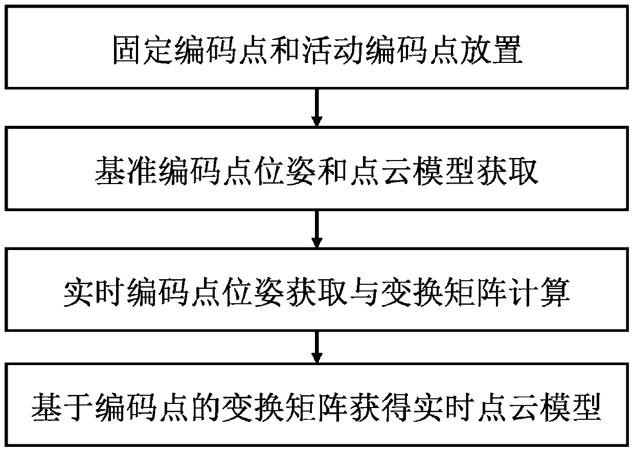
[0046] like figure 1 As shown, a 3D point cloud deformation method driven by coded points is used to detect the deformation state of the moving structure relative to the static structure connected to it, including the following steps:

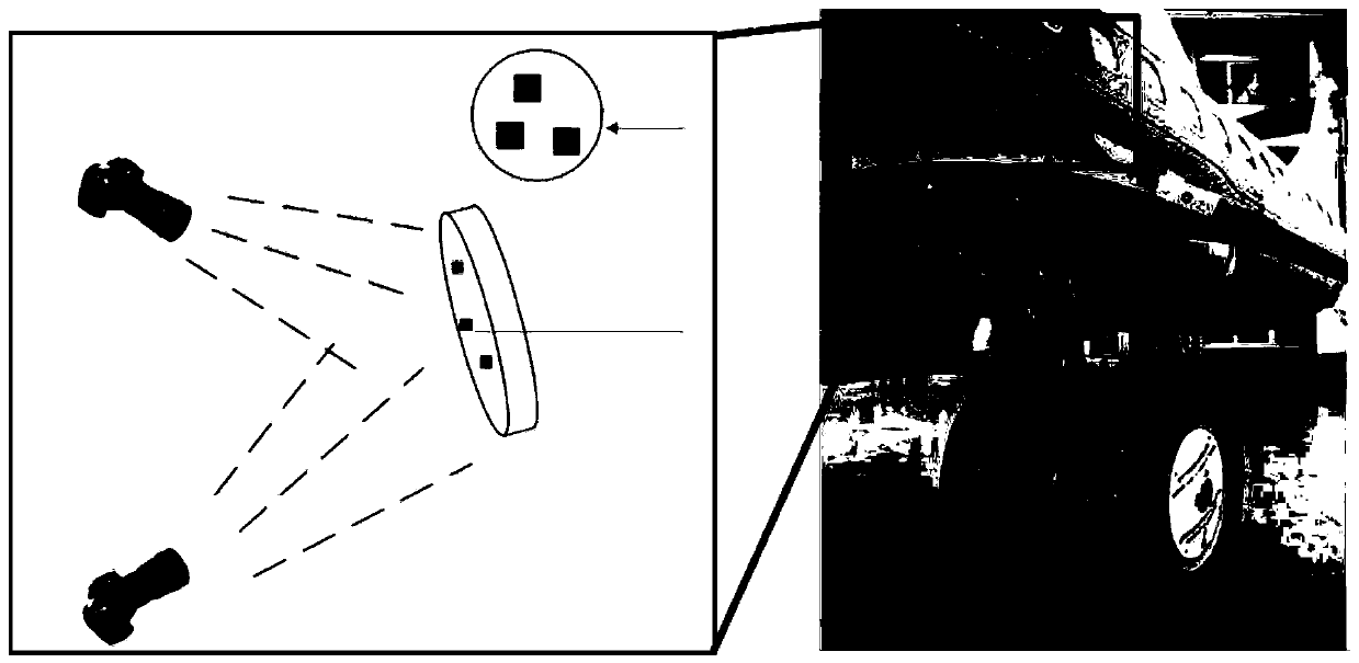
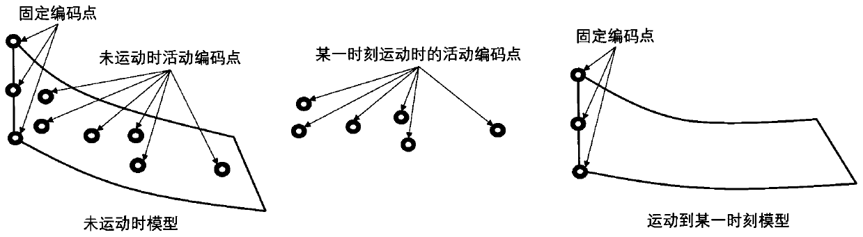
[0047] Step S1, evenly pasting several active code points on the surface of the moving structure, and uniformly pasting some fixed code points on the surface of the static structure;

[0048] The fixed code points pasted on the static structure are used to record the pose changes of the entire part including the moving structure and the static structure, and match the poses of the fixed code points to the reference position at different subsequent moments. The active code points are pasted on the motion structure to record the real-time...


PUM


Abstract

The invention discloses a three-dimensional point cloud deformation method based on coded point driving. According to the method, a three-dimensional scanning point cloud model is combined with dynamic real-time measurement data, double cameras shoot and measure in real time, then a transformation matrix of coding points is calculated, dynamic real-time measurement of the pose of a motion structure is achieved through point cloud transformation and splicing, and the problem that real-time measurement of a part is difficult in the deformation process is solved.

Description

technical field [0001] The invention belongs to the field of aerial surveying, and in particular relates to a three-dimensional point cloud deformation method driven by coded points. Background technique [0002] It has always been a difficult problem to measure the position and deformation of moving parts on the aircraft, deformation and deployment structures (such as wing movable panels, landing gear doors) in the process of movement and deployment in real time. Most of the existing real-time measurement technologies are real-time measurement of static objects or instantaneous measurement of small objects. When large parts are deformed, some structures are in motion. Due to the relatively large structure, use a 3D scanner to obtain a complete point cloud data It takes a certain amount of time, and the measurement of the entire part cannot be completed at the same time. At this time, the point cloud data of the moving structure acquired by the 3D scanner will be distorted a...

Claims


Application Information

Patent Timeline
Patent Type & Authority Applications(China)
IPC IPC(8): G06T19/00G06T9/00
CPCG06T19/006G06T9/001G06T7/55G06T7/251G06T2207/30204G06T2207/30164G06T7/292G06T7/74G06T7/344G06T7/248G06T17/00G06T19/20G06T2207/10028G06T2210/56G06T2219/2021
Inventor 汪俊魏泽勇谢乾
Owner 南京耘瞳科技有限公司
Why Eureka
Try Eureka