The Construction Method of Demolition and Centralized Placement of Exterior Wall Aluminum Formwork
What is AI technical title?
AI technical title is built by PatSnap AI team. It summarizes the technical point description of the patent document.
A construction method and aluminum formwork technology, applied in the field of material stacking, can solve the problems of high safety hazards and achieve the effect of low safety hazards
Active Publication Date: 2021-08-24
深圳市建工集团股份有限公司
View PDF0 Cites 0 Cited by
Summary
Abstract
Description
Claims
Application Information
AI Technical Summary
This helps you quickly interpret patents by identifying the three key elements:
Problems solved by technology
Method used
Benefits of technology
Problems solved by technology
[0005] The purpose of the present invention is to provide a construction method for dismantling the aluminum formwork of the exterior wall and placing it in a centralized manner, aiming to solve the problem in the prior art that materials are stacked on climbing frames and there are high potential safety hazards
Method used
Image
Click on the blue label to locate the original text in one second.
Reading with bidirectional positioning of images and text.
Examples
Embodiment 1
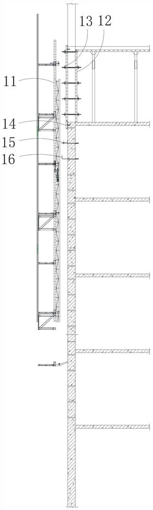
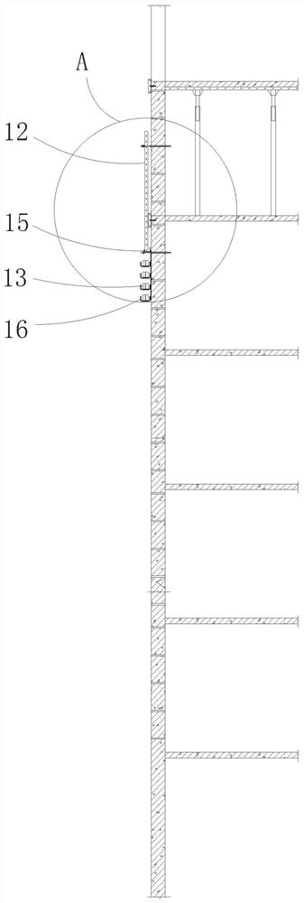
[0071] In the first embodiment, the suspension ring of the suspension rod 161 is hung on the first connecting rod 153, the U-shaped groove 151 is placed on the first connection rod 153, and abuts against the suspension ring of the suspension rod 161, and the U-shaped groove 151 passes through The clamping plate 152 is abutted and fixed, so as to simultaneously fix the U-shaped groove 151 and the suspension rod 161 .
[0072] In this way, in step S50, the cable 154 and the third connecting rod 155 are first disassembled, then the clamping plate 152 is loosened, the U-shaped groove 151 is disassembled, and then the suspension rod 161 and the first connecting rod 153 are dismantled in sequence. , in the installation process, first the first connecting rod 153 is set on the lower wall, then the suspension rod 161 is hung on the first connecting rod 153, and then the U-shaped groove 151 is fixed by the clamping plate 152, and finally The cable 154 and the third connecting rod 155 a...
Embodiment 2
[0073] In the second embodiment, the reinforced main flute 13 is directly hung in the gap between the clamping plate 152 and the U-shaped groove 151 by a sling.
[0074] Like this, in step S50, at first the cable 154 and the third connecting rod 155 are disassembled, then the locking plate 152 is loosened, the U-shaped groove 151 is disassembled, and the first connecting rod 153 is removed. Firstly, the first connecting rod 153 is set on the lower wall, then the U-shaped groove 151 is fixed by the locking plate 152, and finally the cable 154 and the third connecting rod 155 are installed.
[0075] Of course, in other embodiments, the first connecting rod 153 and the second connecting rod 163 may also have different structures, which will not be repeated here.
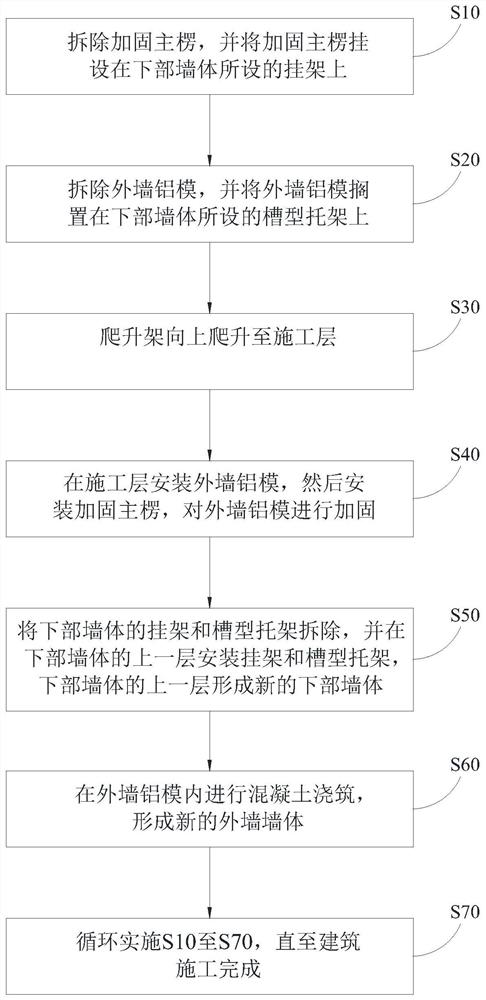
[0076] Please refer to figure 1 , in an embodiment of the present invention, after step S40:
[0077]The K board 14 of the lower body of wall is removed, and the K board 14 is installed on the top of the construction ...
PUM
Abstract
The invention relates to the technical field of material stacking, and discloses a construction method for dismantling and placing aluminum formwork on exterior walls together, including the following steps: S10, removing and reinforcing the main flute, and hanging the reinforced main flute on the hanger provided on the lower wall on the frame; S20, remove the aluminum formwork of the external wall, and place the aluminum formwork on the lower wall on the groove bracket; S30, climb up the climbing frame to the construction layer; S40, install the aluminum formwork on the construction layer mold, then install and reinforce the main flute, and reinforce the aluminum mold of the exterior wall; S50, remove the hanger and groove bracket on the lower wall, and install the hanger and groove bracket on the upper layer of the lower wall , the upper layer of the lower wall forms a new lower wall; S60, pours concrete in the aluminum formwork of the outer wall to form a new outer wall; S70, implements S10 to S70 cyclically until the building construction is completed. The construction method in which the exterior wall aluminum formwork is dismantled and placed centrally provided by the technical proposal of the present invention avoids placing the exterior wall aluminum formwork on the climbing frame, and can reduce the safety hazard of material placement.
Description
technical field [0001] The patent of the present invention relates to the technical field of material stacking, and specifically relates to a construction method for dismantling and placing aluminum formwork for exterior walls. Background technique [0002] In the construction industry, the aluminum formwork is assembled and combined, and then the concrete is poured, and then the wall structure of the building can be obtained. The application of the aluminum formwork system improves the construction efficiency of the housing construction project, and reduces the cost of building materials and labor. Saved a lot. Generally, it is widely used in the construction of high-rise buildings. [0003] At present, in the construction process of high-rise buildings, after the outer wall is formed, the aluminum formwork of the outer wall needs to be removed, and then the climbing frame is climbed accordingly, and the construction continues upward. [0004] However, during the climbing...
Claims
Application Information
Patent Timeline
Application Date:The date an application was filed.
Publication Date:The date a patent or application was officially published.
First Publication Date:The earliest publication date of a patent with the same application number.
Issue Date:Publication date of the patent grant document.
PCT Entry Date:The Entry date of PCT National Phase.
Estimated Expiry Date:The statutory expiry date of a patent right according to the Patent Law, and it is the longest term of protection that the patent right can achieve without the termination of the patent right due to other reasons(Term extension factor has been taken into account ).
Invalid Date:Actual expiry date is based on effective date or publication date of legal transaction data of invalid patent.

