Driving mechanism and air outlet equipment applying same

A driving mechanism, air inlet and outlet technology, applied in mechanical equipment, machines/engines, liquid fuel engines, etc., can solve the problems of adjustment of blowing parameters, low blowing comfort, inability to change the outlet and direction, etc. Variety of states, good user experience, and a wide range of effects

Active Publication Date: 2020-08-18
FOSHAN VIOMI ELECTRICAL TECH +1
View PDF10 Cites 0 Cited by
  • Summary
  • Abstract
  • Description
  • Claims
  • Application Information

AI Technical Summary

Problems solved by technology

[0005] However, in the prior art, no matter whether it adopts multi-section swing leaves, multiple air outlets or multi-section fuselage independent swing schemes, it is only on the basis of traditional column fans or air conditioners, and the traditional single air outlet or direction of the air outlet equipment. Structurally increased to have two or three or more independent air outlets or directions; to a certain extent, the air outlet device can be blown in multiple directions independently or at the same time, but because these air outlet devices are assembled, once they leave the factory , the structure of the air outlet equipment has been fixed, the number of air outlets and the direction of air outlets have been fixed, and the number and use parameters of the air outlets and directions cannot be changed in real time according to the usage scenarios or the actual situation of the user.
Therefore, in terms of the flexibility of the use structure, the use mode of the existing air outlet equipment is very limited, and the blowing parameters cannot be adjusted according to the actual use situation, and the blowing comfort is not high

Method used


Image

  • Driving mechanism and air outlet equipment applying same
  • Driving mechanism and air outlet equipment applying same
  • Driving mechanism and air outlet equipment applying same

Examples


specific Embodiment approach 1

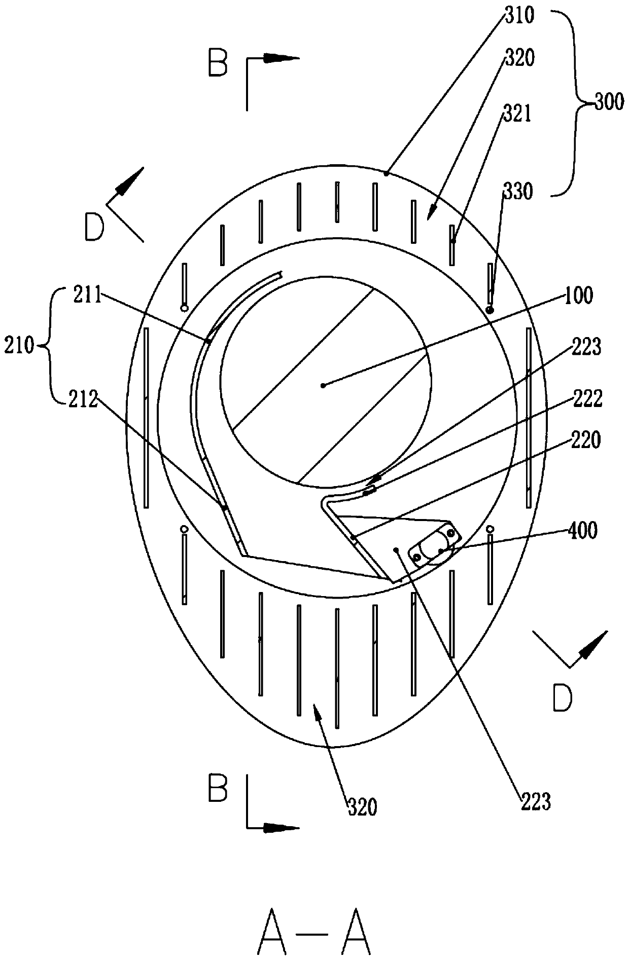
[0045] Embodiment 1: the driving gear 410 is a cylindrical gear, and the unit driving device 400 is installed on the air guide structure or the mounting bracket; the air channel layer structure is ring-shaped, and the inner ring is circular; the The driving gear 410 rotates in the horizontal plane; the ring rack is arranged along the inner ring of the air channel layer structure. In this solution, the drive mechanism is mainly distributed in the horizontal direction, which can make the installation structure of the air inlet and outlet array mechanism more precise in the vertical direction. The specific installation structure of the ring rack can also be: the inner ring of the air duct layer structure may not be set to be circular, and the ring rack can pass through a plurality of columns and the inner ring of the air duct layer structure The connection is fixed.

specific Embodiment approach 2

[0046] Embodiment 2: The driving gear 410 is a cylindrical gear, and the unit driving device 400 is installed on the wind guide structure or the mounting bracket; the driving gear 410 rotates in the horizontal plane; the ring rack is in the form of a ring shape, and is arranged on the upper surface or the lower surface of the air duct layer structure. In this solution, the driving mechanism is mainly distributed in the vertical direction, which can make the installation structure of the air inlet and outlet array mechanism more precise in the horizontal direction. In addition, the weight of the air duct layer structure can be driven by the unit As for the device, in the sub-plan, the interlayer support structures such as support columns can be simplified and not set up between the air duct layer structures.

[0047] During the use of the air outlet device, if the air duct layer structure can be driven horizontally, each layer of the air duct layer structure will not appear che...


PUM


Abstract

The invention relates to the field of electric appliances, in particular to a driving mechanism and air outlet equipment applying the driving mechanism. The driving mechanism comprises a plurality oflayers of air duct layer structures stacked up and down, and is characterized by comprising a plurality of unit driving devices and driving parts which are in transmission fit with each unit driving device; the driving parts are arranged on the air duct layer structures, and the unit driving devices are used for driving the air duct layer structures at the corresponding positions to horizontally rotate relative to the air guide structures. The driving mechanisms adopt the independent unit driving devices to respectively drive each layer of air duct layer structure to rotate, so that an air inlet and outlet array mechanism arranged on the air outlet equipment can flexibly and quickly control the air outlet direction; according to the air outlet equipment, the air outlet working state can berapidly adjusted in real time according to the using environment and the user condition, the using state of the air outlet equipment is more diversified, the application range is wider, and the usingexperience of a user is better.

Description

technical field [0001] The invention relates to the field of electrical appliances, in particular to a driving mechanism and an air outlet device using the same. Background technique [0002] There are many types of equipment with air outlet function in the field of electrical appliances, such as fans, air conditioners, heaters and air purifiers, etc. Among them, the column fan and air conditioner (indoor unit) are beautiful in overall design, occupy a small space, and have good air output. The performance is better than traditional air outlet equipment, and it is widely used in family life. However, the existing column fans and air conditioners also have obvious defects. For example, due to the cylindrical shell, the fixed flexibility of the internal air outlet structure is not high enough, and it cannot blow air in multiple different directions or areas at the same time. It can only be oscillated by setting The air-guiding grille swings back and forth in different directi...

Claims


Application Information

Patent Timeline
IPC IPC(8): F04D29/46F04D17/04F04D25/08F04D29/42F04D29/66
CPCF04D29/462F04D29/4246F04D25/08F04D17/04F04D29/661
Inventor 陈小平唐清生
Owner FOSHAN VIOMI ELECTRICAL TECH
Why Eureka
Try Eureka