Linkage mechanism, air outlet array mechanism and air outlet equipment

A linkage mechanism and air outlet technology, which is applied to mechanical equipment, machines/engines, liquid fuel engines, etc., can solve problems such as the inability to change the air outlet and direction, adjustment of the use of blowing parameters, and limited use modes of air outlet equipment, etc., to achieve Diversified use states, good user experience, wide range of effects

Active Publication Date: 2020-06-19
FOSHAN VIOMI ELECTRICAL TECH +1
View PDF12 Cites 0 Cited by
  • Summary
  • Abstract
  • Description
  • Claims
  • Application Information

AI Technical Summary

Problems solved by technology

[0005] However, in the prior art, no matter whether it adopts multi-section swing blades, multiple air outlets or multi-section fuselage independent swing schemes, it is only on the basis of traditional column fans or air conditioners, and the traditional single air outlet or direction of the air outlet equipment. Structurally increased to have two or three or more independent air outlets or directions; to a certain extent, the air outlet device can be blown in multiple directions independently or at the same time, but because these air outlet devices are assembled, once they leave the factory , the structure of the air outlet equipment has been fixed, the number of air outlets and the direction of air outlets have been fixed, and the number and use parameters of the air outlets and directions cannot be changed in real time according to the usage scenarios or the actual situation of the user.
Therefore, in terms of the flexibility of the use structure, the use mode of the existing air outlet equipment is very limited, and the blowing parameters cannot be adjusted according to the actual use situation, and the blowing comfort is not high

Method used


Image

  • Linkage mechanism, air outlet array mechanism and air outlet equipment
  • Linkage mechanism, air outlet array mechanism and air outlet equipment
  • Linkage mechanism, air outlet array mechanism and air outlet equipment

Examples


Embodiment 1

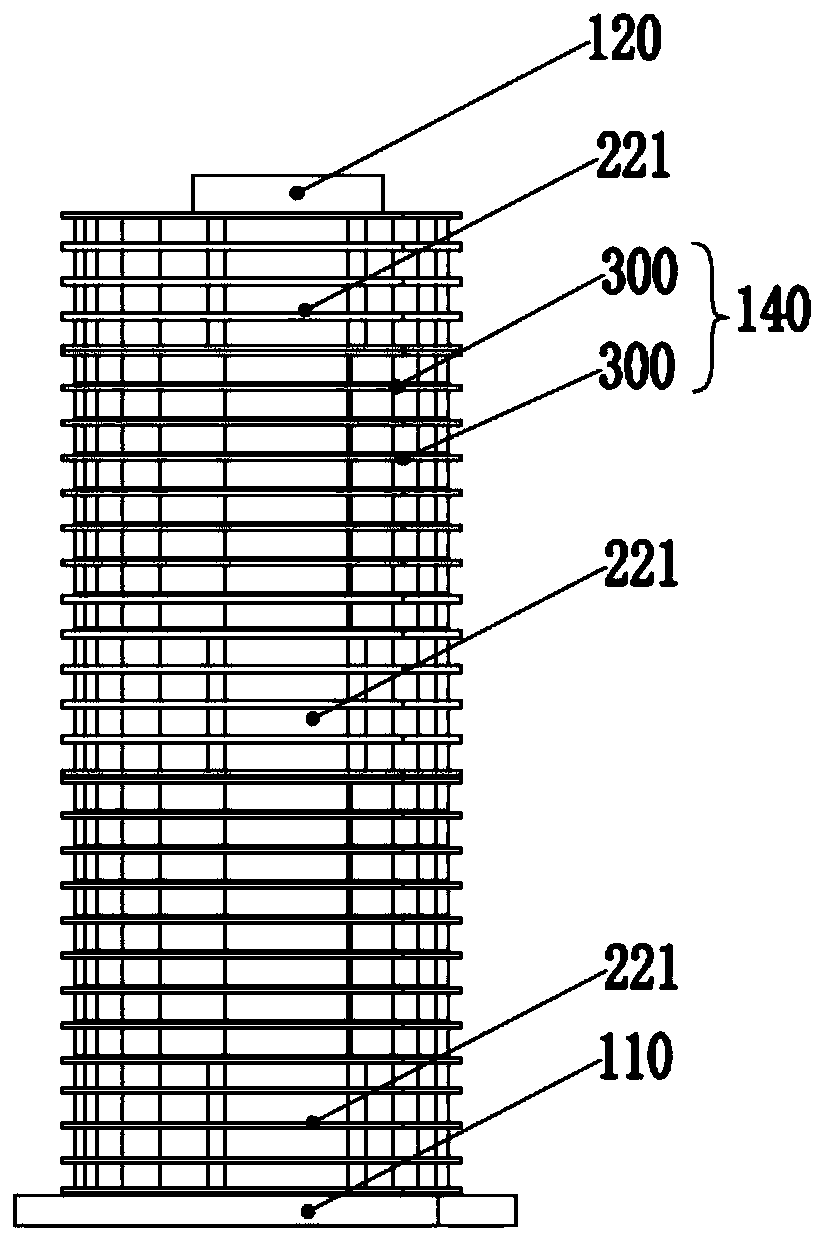
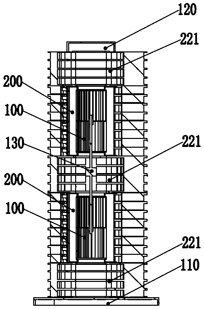
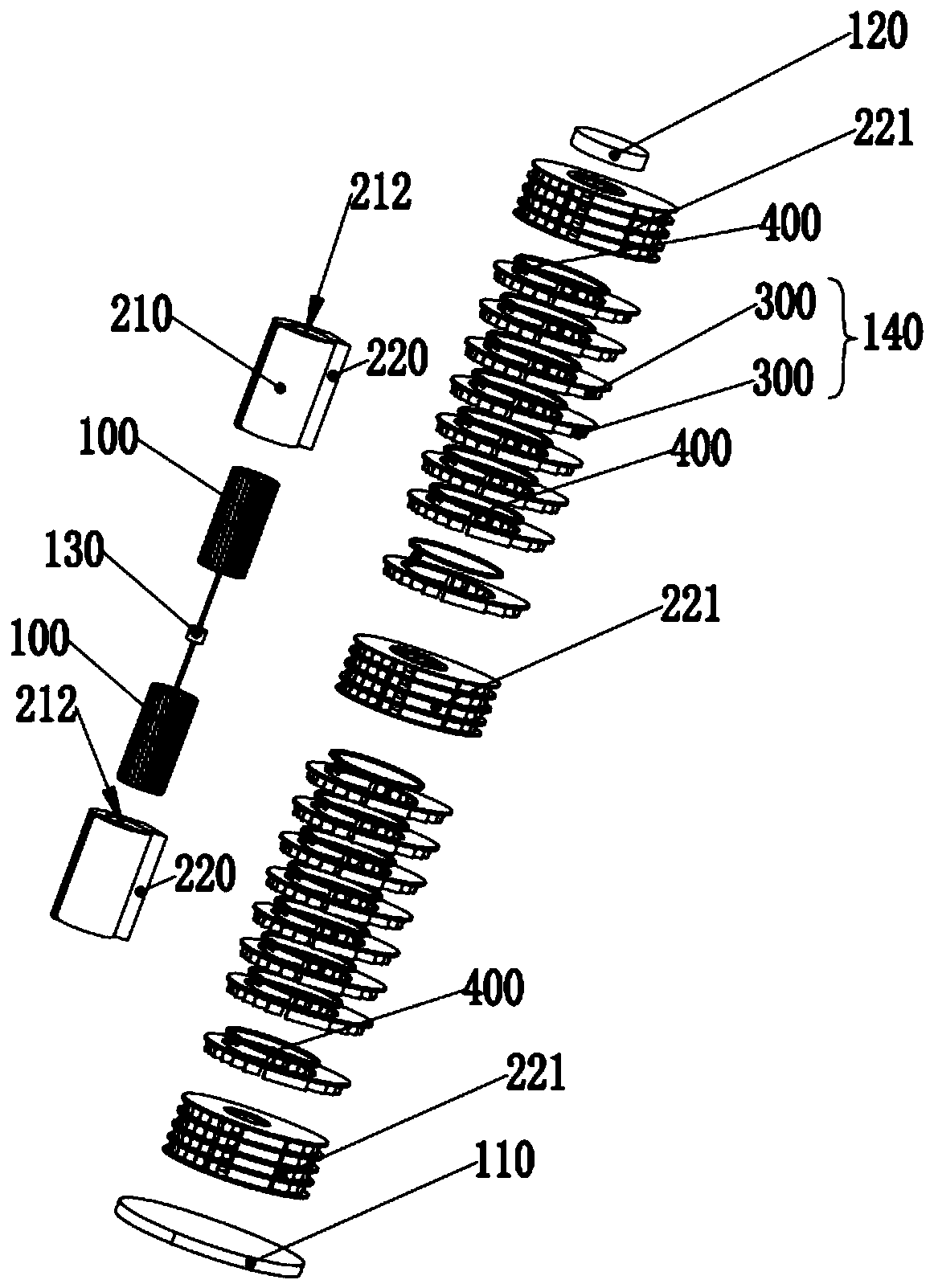
[0036] Such as Figure 1-7 As shown, an air outlet device includes: a centrifugal wind wheel 100, a wind wheel driving device 130, an air guide volute 210, and an air outlet array mechanism 140; the air outlet array mechanism 140 includes: The air channel layer structure; the air channel layer structure is a ring structure, and the middle part of the ring structure is provided with a hollowed out middle area; the centrifugal wind wheel 100 is vertically arranged in the wind guide volute 210, and is connected with the wind The wheel driving device 130 is connected by transmission; the side of the wind guide volute 210 is horizontally provided with an air outlet window 211, and the top and / or bottom of the wind guide volute 210 is provided with an air inlet 212; the air outlet array mechanism 140 The cover is arranged on the outside of the wind guiding volute 210 ; the air channel layer structure can rotate independently or combined horizontally around the wind guiding volute 21...

Embodiment 2

[0054] On the basis of Embodiment 1, an air outlet device is proposed, which also includes two sections of the air outlet array mechanism 140. Compared with Embodiment 1, the difference is that the two sections of the air outlet array mechanism in Embodiment 1 The driving mode and activity mode of 140 are the same, and a plurality of unit driving devices are used to respectively drive the rotation of the air duct layer structure of each layer; Embodiment On the basis of Embodiment 1, the air outlet array mechanism 140 described in the preceding paragraph is modified. Such as Figure 8 with 9 As shown, the specific implementation of the air outlet array mechanism 140 located in the upper section of the air outlet device is as follows:

[0055]The air outlet array mechanism 140 includes: a multi-layered air duct layer structure; the air duct layer structure is divided into an active layer and a linkage layer, and the active layer is located in the air outlet array mechanism 14...

Embodiment 3

[0061] On the basis of Embodiment 1, an air outlet device is proposed, which also includes two sections of the air outlet array mechanism 140. Compared with Embodiment 1, the difference is that the two sections of the air outlet array mechanism in Embodiment 1 The driving mode and activity mode of 140 are the same, and a plurality of unit driving devices are used to respectively drive the rotation of the air duct layer structure of each layer; the driving mode and activity mode of the air outlet array mechanism 140 described in the two sections in this embodiment are Differently, this embodiment modifies the air outlet array mechanism 140 described in the preceding paragraph on the basis of the first embodiment. Such as Figure 10-12 As shown, the specific implementation of the air outlet array mechanism 140 located in the upper section of the air outlet device is as follows:

[0062] The air outlet array mechanism 140 includes: a multi-layered air duct layer structure; the a...


PUM


Abstract

The invention relates to the field of electric appliances, in particular to a linkage mechanism, an air outlet array mechanism and air outlet equipment. The linkage mechanism and the air outlet arraymechanism are applied to the air outlet equipment. The air outlet array mechanism comprises multiple layers of air duct layer structures which are stacked up and down, the air outlet array mechanism is provided with the multiple layers of air duct layer structures, and the adjacent air duct layer structures of the air outlet array mechanism are connected through flexible connecting pieces, so thatlinkage rotation of the air outlet array mechanism is achieved under the action of a driving mechanism. According to the air outlet array mechanism, in the rotating process of the air duct layer structures, the air outlet direction, the air volume or the turbulence number of the air outlet equipment can be adjusted, and an equipment shell for limiting an air inlet and outlet area is not arrangedso that the air outlet equipment can rapidly adjust the air outlet working condition in real time according to the using environment and the user condition, and compared with existing air outlet equipment, the air outlet equipment is flexible in structure, diversified in using states, wider in application range and capable of bringing better using experience to users.

Description

technical field [0001] The invention relates to the field of electrical appliances, in particular to a linkage mechanism, an air outlet array mechanism and an air outlet device. Background technique [0002] There are many types of equipment with air outlet function in the field of electrical appliances, such as fans, air conditioners, heaters and air purifiers, etc. Among them, the column fan and air conditioner (indoor unit) are beautiful in overall design, occupy a small space, and have good air output. The performance is better than traditional air outlet equipment, and it is widely used in family life. However, the existing column fans and air conditioners also have obvious defects. For example, due to the cylindrical shell, the fixed flexibility of the internal air outlet structure is not high enough, and it cannot blow air in multiple different directions or areas at the same time. It can only be oscillated by setting The air-guiding grille swings back and forth in d...

Claims


Application Information

Patent Timeline
Patent Type & Authority Applications(China)
IPC IPC(8): F04D29/46F04D17/16F04D25/08F04D25/16F04D29/42
CPCF04D17/16F04D25/08F04D25/166F04D29/4246F04D29/462
Inventor 陈小平唐清生
Owner FOSHAN VIOMI ELECTRICAL TECH
Why Eureka
Try Eureka