Air outlet equipment

A technology of equipment and air outlet, applied in the field of air outlet equipment, can solve the problems of adjustment of blowing parameters, low comfort of blowing, and inability to change the air outlet and direction, etc., to achieve the effect of wide application range and good user experience

Active Publication Date: 2020-06-19
FOSHAN VIOMI ELECTRICAL TECH +1
View PDF11 Cites 0 Cited by
  • Summary
  • Abstract
  • Description
  • Claims
  • Application Information

AI Technical Summary

Problems solved by technology

[0005] However, in the prior art, no matter whether it adopts multi-section swing blades, multiple air outlets or multi-section fuselage independent swing schemes, it is only on the basis of traditional column fans or air conditioners, and the traditional single air outlet or direction of the air outlet equipment. Structurally increased to have two or three or more independent air outlets or directions; to a certain extent, the air outlet device can be blown in multiple directions independently or at the same time, but because these air outlet devices are assembled, once they leave the factory , the structure of the air outlet equipment has been fixed, the number of air outlets and the direction of air outlets have been fixed, and the number and use parameters of the air outlets and directions cannot be changed in real time according to the usage scenarios or the actual situation of the user.
Therefore, in terms of the flexibility of the use structure, the use mode of the existing air outlet equipment is very limited, and the blowing parameters cannot be adjusted according to the actual use situation, and the blowing comfort is not high

Method used


Image

  • Air outlet equipment
  • Air outlet equipment
  • Air outlet equipment

Examples


Embodiment Construction

[0053] The technical solutions of the present invention will be further described below in conjunction with the accompanying drawings and through specific implementation methods.

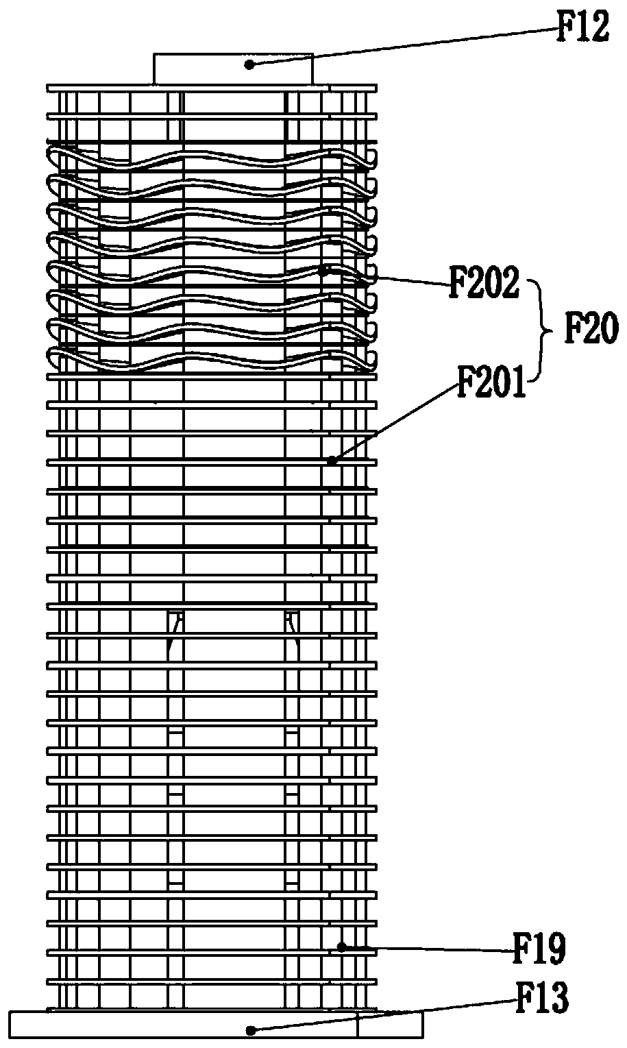
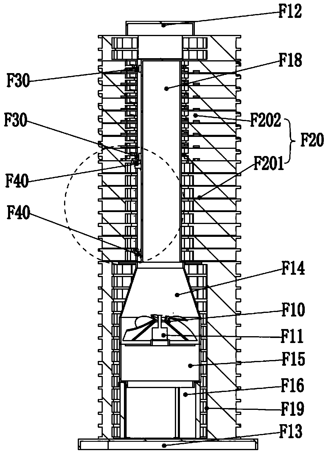
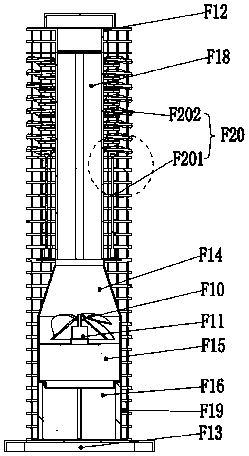
[0054] Such as Figure 1-14 As shown, an air outlet device includes an air outlet device and an air outlet array mechanism F20; the air outlet device includes: an oblique flow wind wheel F10, a wind wheel driving device F11 and an air duct housing; the air outlet array mechanism F20 includes : multi-layer air duct layer structure stacked up and down; the middle part of the air outlet array mechanism F20 is vertically provided with a middle air duct F18; Wind window part F181; the top of the air duct shell is provided with an air outlet, and the bottom is provided with an air inlet; one end of the middle air duct F18 communicates with the air outlet of the air outlet device, and the other end of the middle air duct F18 One end is provided with a blocking structure; the wind wheel driving device F11 ...


PUM


Abstract

The invention relates to the field of electric appliances, in particular to air outlet equipment. The air outlet equipment comprises an air outlet device and an air outlet array mechanism. The air outlet array mechanism comprises multiple layers of air duct layer structures which are stacked up and down, and the air outlet array mechanism is provided with the multiple layers of air duct layer structures and a middle air duct; and an air outlet is formed in the top of the air outlet device, and an air inlet is formed in the bottom of the air outlet device. Each air duct layer structure can be driven by external force to rotate independently or in a combined mode, air outlet parameters such as the air outlet direction, the air volume or the turbulence degree of the air outlet equipment are adjusted according to use requirements, the air outlet equipment is not provided with an equipment shell, and all-dimensional air outlet can be achieved. According to the air outlet equipment, the airoutlet working condition can be adjusted in real time according to the using environment and the user condition, and compared with existing air outlet equipment, the air outlet equipment is simple andingenious in structure, more diversified in using state, wider in application range and capable of providing better using experience for users.

Description

technical field [0001] The invention relates to the field of electrical appliances, in particular to an air outlet device. Background technique [0002] There are many types of equipment with air outlet function in the field of electrical appliances, such as fans, air conditioners, heaters and air purifiers, etc. Among them, the column fan and air conditioner (indoor unit) are beautiful in overall design, occupy a small space, and have good air output. The performance is better than traditional air outlet equipment, and it is widely used in family life. However, the existing column fans and air conditioners also have obvious defects. For example, due to the cylindrical shell, the fixed flexibility of the internal air outlet structure is not high enough, and it cannot blow air in multiple different directions or areas at the same time. It can only be oscillated by setting The air-guiding grille swings back and forth in different directions to achieve alternate blowing. This ...

Claims


Application Information

Patent Timeline
Patent Type & Authority Applications(China)
IPC IPC(8): F04D25/08F04D29/40
CPCF04D25/08F04D29/403
Inventor 陈小平唐清生
Owner FOSHAN VIOMI ELECTRICAL TECH
Why Eureka
Try Eureka