Air conditioner debugging system and method for confirming capillary tube length

A debugging system and capillary technology, applied in space heating and ventilation details, heating and ventilation control systems, heating and ventilation safety systems, etc., can solve problems such as long time-consuming and cumbersome capillary process, and achieve short time-consuming and labor-saving , the effect of shortening the time

Inactive Publication Date: 2020-08-18
NINGBO AUX ELECTRIC +1
View PDF7 Cites 1 Cited by
  • Summary
  • Abstract
  • Description
  • Claims
  • Application Information

AI Technical Summary

Problems solved by technology

[0003] The present invention aims to propose an air conditioner debugging system and a method for determining the length of the capillary, so as to solve the technical problems of cumbersome and time-consuming determination of the target capillary in the prior art

Method used


Image

  • Air conditioner debugging system and method for confirming capillary tube length
  • Air conditioner debugging system and method for confirming capillary tube length
  • Air conditioner debugging system and method for confirming capillary tube length

Examples


Embodiment 1

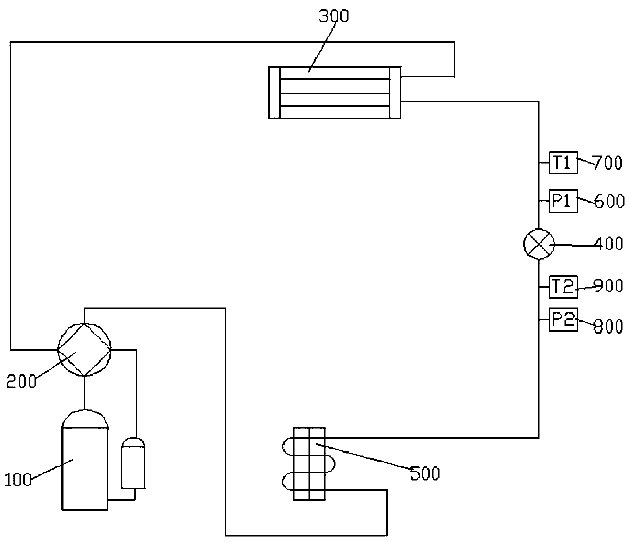
[0060] This embodiment discloses an air conditioner debugging system, which is used to determine the capillary length, such as figure 1As shown, the air conditioning debugging system includes a compressor 100, a four-way valve 200, a condenser 300, and an evaporator 400 connected in sequence, and an electronic expansion valve 500 is arranged between the condenser 300 and the evaporator 400, and the inlet of the electronic expansion valve 500 A first pressure sensor 600 and a first temperature sensor 700 are installed, and an outlet of the electronic expansion valve 500 is installed with a second pressure sensor 800 and a second temperature sensor 900 .

[0061] In this embodiment, preferably, the air conditioning debugging system includes a controller, and the controller is respectively connected to the compressor 100, the electronic expansion valve 500, the first pressure sensor 600, the first temperature sensor 700, the second pressure sensor 800 and the second temperature se...

Embodiment 2

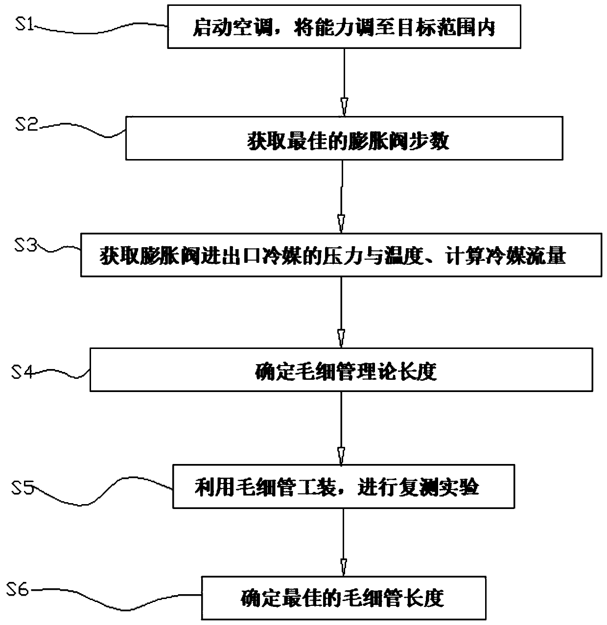
[0064] This embodiment discloses a method for determining the length of the capillary, using the air conditioning debugging system in Embodiment 1, such as figure 2 As shown, methods for determining capillary length include:

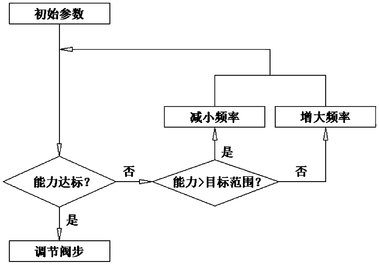
[0065] S1. Start the air conditioning debugging system, set the parameters according to the experience value, adjust the frequency of the compressor, and adjust the capacity to the target range;

[0066] S2. With the best energy efficiency as the goal, adjust the valve step of the electronic expansion valve to obtain the number of steps of the electronic expansion valve when the energy efficiency is the best;

[0067] S3. Obtain the pressure and temperature at the inlet and outlet of the electronic expansion valve 500 when the energy efficiency is the best, and calculate the refrigerant flow rate in the air conditioning debugging system;

[0068] S4. According to the pressure and temperature at the inlet and outlet of the electronic expansion valve 500...


PUM


Abstract

The invention discloses an air conditioner debugging system and a method for confirming the capillary tube length. The air conditioner debugging system comprises a compressor, a four-way valve, a condenser and an evaporator which are connected in sequence, and an electronic expansion valve is arranged between the condenser and the evaporator. According to the air conditioner debugging system and the method for confirming the capillary tube length, the theoretical capillary tube length is calculated according to all parameters of the air conditioner debugging system in the best energy efficiency, the best capillary tube length can be obtained just needing to test two sets of capillary tubes after the theoretical capillary tube length is obtained, vacuumizing and gas injection operations donot need to be performed on a pipeline system repeatedly, manual and frequent replacement of the capillary tube length is also not needed, the optimal capillary tube length is rapidly, effectively andaccurately confirmed, the process is simple, time consuming is short, and manpower, material resources and time are saved.

Description

technical field [0001] The invention relates to the technical field of air conditioning, in particular to an air conditioning debugging system and a method for determining the length of a capillary. Background technique [0002] As an important part of the air conditioner, the capillary has a good effect of throttling and reducing pressure. When the air conditioner is running, the high-pressure and high-temperature refrigerant output from the high-pressure end of the compressor flows through the capillary tube and becomes a low-pressure and high-temperature gas. As a throttling device, the capillary has the characteristics of simple structure, low cost and high reliability. Therefore, it is widely used in air conditioning systems. However, in the early debugging of the air conditioner, it is necessary to repeatedly replace the capillary and conduct a large number of experiments to determine the optimal length, which consumes a lot of manpower, material resources and time, ...

Claims


Application Information

Patent Timeline
Patent Type & Authority Applications(China)
IPC IPC(8): F24F11/49F24F11/64F24F11/84F24F11/86F24F11/88F24F13/30
CPCF24F13/30F24F11/49F24F11/64F24F11/84F24F11/86F24F11/88
Inventor 兰加芬黄松斌应必业
Owner NINGBO AUX ELECTRIC
Why Eureka
Try Eureka