High water pressure waterproof micro speaker

A micro-speaker, high water pressure technology, applied in speaker screens, speaker housing brackets, transducers used underwater, etc., can solve problems such as affecting the waterproof failure rate, and achieve the effect of reducing waterproof failure and uniform combination.

Active Publication Date: 2021-07-23
EM TECHNOLOGY CO LTD
View PDF7 Cites 0 Cited by
  • Summary
  • Abstract
  • Description
  • Claims
  • Application Information

AI Technical Summary

Problems solved by technology

Therefore, the amount of adhesive applied, the location of application and the bonding pressure will affect the failure rate of waterproofing
Another disadvantage is that the waterproofing failure rate is affected by how well the waterproofing tape remains free of foreign matter and the amount of compression since audio components are assembled to electronic devices using waterproofing tape

Method used


Image

  • High water pressure waterproof micro speaker
  • High water pressure waterproof micro speaker
  • High water pressure waterproof micro speaker

Examples


Embodiment Construction

[0017] Hereinafter, the present invention will be described in more detail with reference to the accompanying drawings.

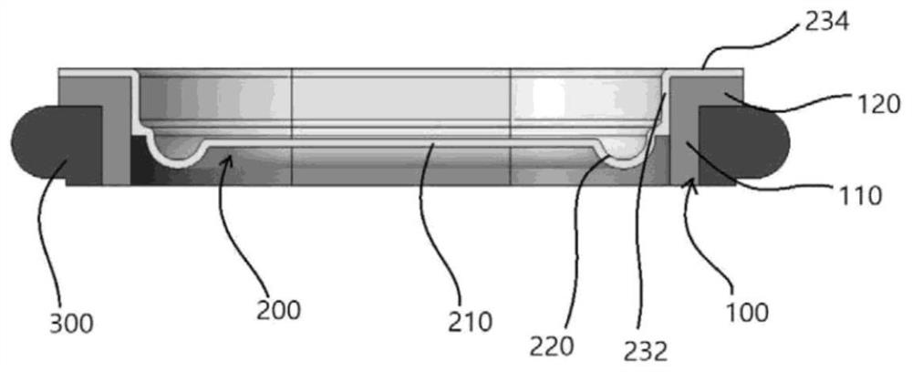
[0018] figure 2 is a view showing a high water pressure waterproof microspeaker according to an exemplary embodiment of the present invention.

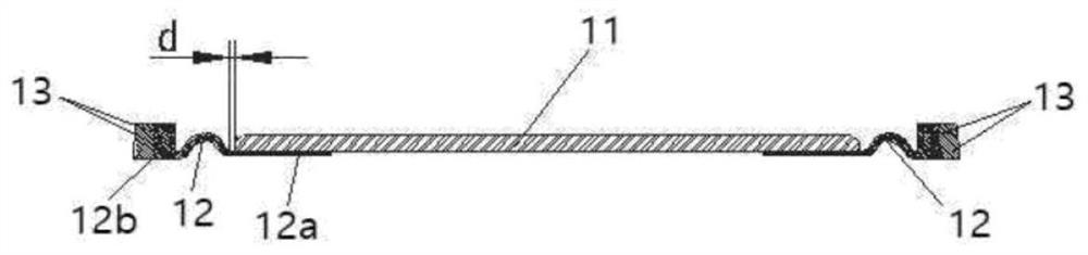
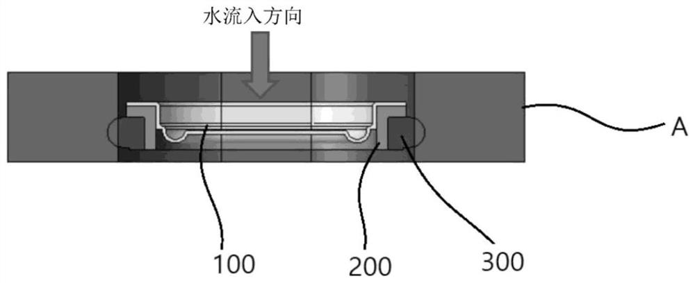
[0019] The high water pressure waterproof micro speaker according to the exemplary embodiment of the present invention includes a frame 100 and a vibrating part inside the frame 100, and the vibrating part includes a diaphragm 200 and a vibrating member vibrating the diaphragm 200. The vibration member may be a generally used voice coil (not shown) and magnetic circuit (not shown), or may be a piezoelectric element attached to the diaphragm 200 .

[0020] The frame 100 includes a side wall 110 and a flange portion 120 extending outward from an upper edge of the side wall 110 . The aforementioned vibrating part is placed in a space defined by the side wall 110 . The frame 100 may be made of steel or injection mo...


PUM


Abstract

An object of the present invention is to provide a waterproof speaker with a waterproof rating of 8 or above, which can provide a waterproof function under high water pressure. The present invention provides a high water pressure waterproof loudspeaker, which has a frame and a vibrating part inside the frame. a diaphragm inside the frame; and a waterproof ring placed on a side wall of the frame and configured to protrude outwardly from the flange portion of the frame.

Description

technical field [0001] The invention relates to a high water pressure waterproof loudspeaker. Background technique [0002] Mobile devices have tiny speakers that play user notification sounds or audio content. More and more mobile devices are equipped with daily life waterproofing to maximize the convenience of mobile devices. The need to make microspeakers installed in mobile devices waterproof is in line with this trend. [0003] figure 1 is a view showing a waterproof microspeaker structure disclosed in Korean Patent Registration No. 10-1889315 according to conventional technology. The main body of the diaphragm comprises a rigid top part 11 , a silicone rubber membrane 12 and a plastic support 13 attached to the edge of the silicone rubber membrane 12 . The silicone rubber film 12 includes: a flat attaching portion 12a positioned at the center; a connecting portion 12b positioned at the edge and injection molded and attached to the plastic support 13; and positioned...

Claims


Application Information

Patent Timeline
Patent Type & Authority Patents(China)
IPC IPC(8): H04R9/06H04R9/02H04R1/44
CPCH04R1/44H04R9/02H04R9/06H04R1/023H04R1/026H04R7/22H04R31/003H04R2307/00H04R2400/00H04R2400/11H04R2499/11H04R7/18H04R7/04
Inventor 金千明郑性哲洪性珍
Owner EM TECHNOLOGY CO LTD
Why Eureka
Try Eureka