Eureka AIR delivers breakthrough ideas for toughest innovation challenges, trusted by R&D personnel around the world.

Wind-driven curtain wall structure with swing shafts

A kind of pneumatic and curtain wall technology, applied in the direction of walls, building components, building structures, etc., can solve the problems of unsightly, inconsistent, loose state of pneumatic sheets, etc., and achieve the effect of overall beauty, consistent angle, and stable structure.

Pending Publication Date: 2020-08-21
东莞格誉节能科技有限公司
View PDF0 Cites 1 Cited by
  • Summary
  • Abstract
  • Description
  • Claims
  • Application Information

AI Technical Summary

Problems solved by technology

[0004] The invention provides a wind-driven curtain wall structure with a pendulum shaft to solve the problems of loose or different states of the wind-driven pieces and unsightly appearance

Method used


Image

  • Wind-driven curtain wall structure with swing shafts
  • Wind-driven curtain wall structure with swing shafts
  • Wind-driven curtain wall structure with swing shafts

Examples


Embodiment Construction

[0034] In order to have a clearer understanding of the technical features, purposes and effects of the present invention, the present invention will now be described with reference to the accompanying drawings.

[0035] The invention provides a pneumatic curtain wall structure, which has the advantages of firm, reliable and stable structure, durable pneumatic curtain wall and the like.

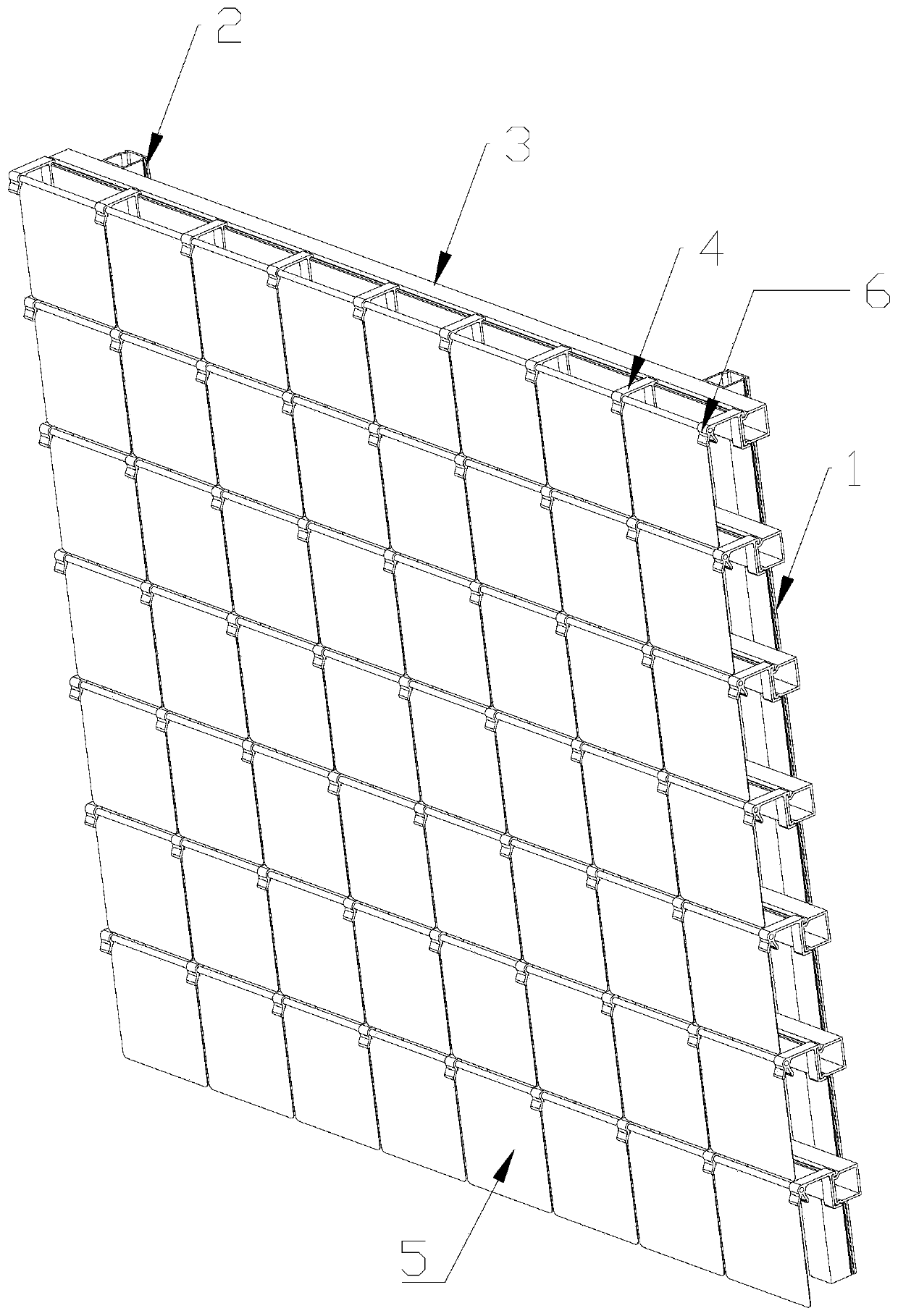
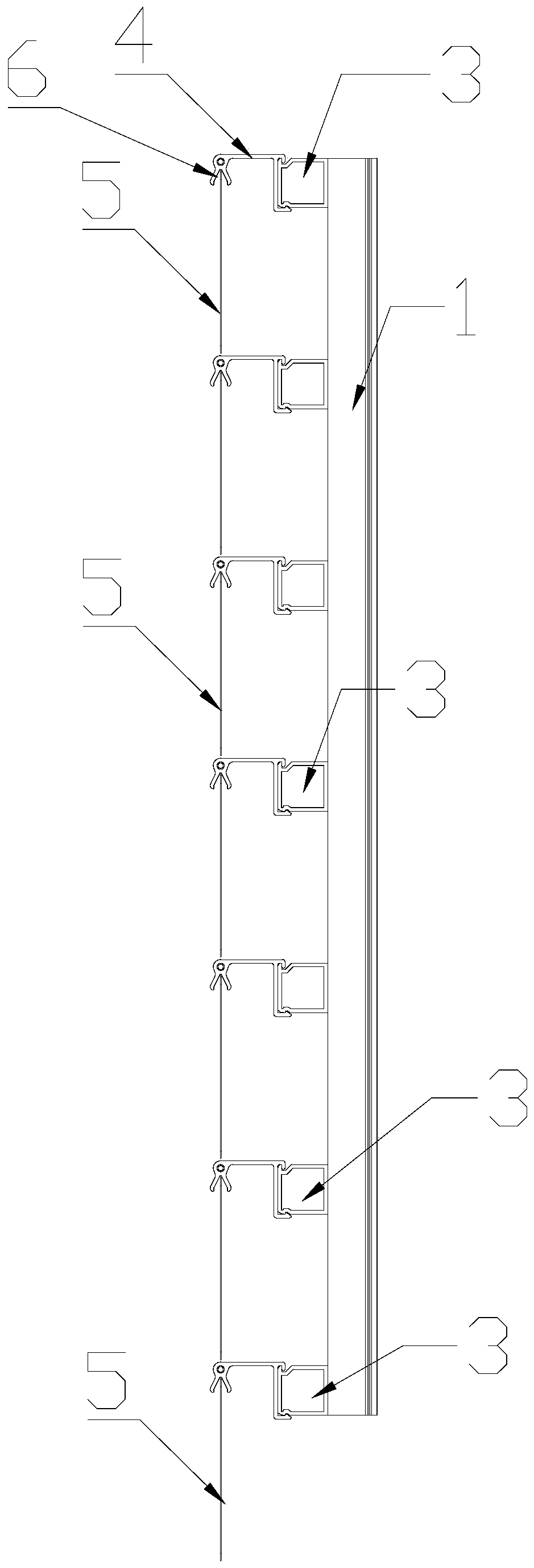
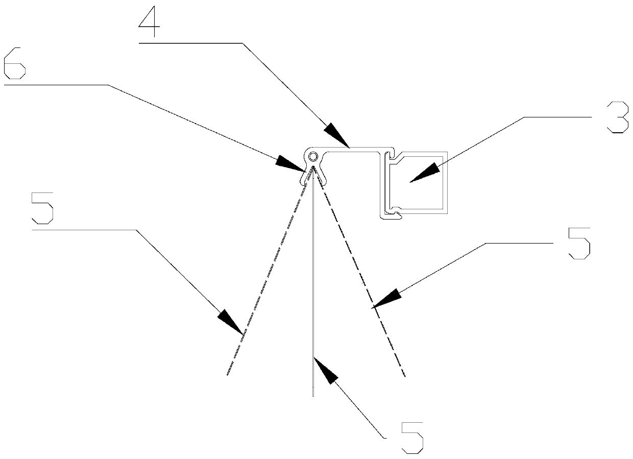
[0036] For this reason, the present invention proposes a kind of pneumatic curtain wall structure with pendulum shaft, as figure 1 , figure 2 and image 3 As shown, the wind-driven curtain wall structure includes:

[0037] The first vertical support 1, the second vertical support 2 parallel to the first vertical support 1; the first vertical support 1 and the second vertical support 2 are hollow pipes, such as aluminum profiles or plastic steel , used to support the entire structure, the structure is light, easy to install and punch;

[0038] Horizontal support 3, the number of the horizo...


PUM


Abstract

The invention provides a wind-driven curtain wall structure with swing shafts. The wind-driven curtain wall structure includes a transverse support, a plurality of wind-driven piece connection devices, a plurality of wind-driven pieces, first shaft sleeves and the swing shafts. The wind-driven piece connection devices are arranged on the transverse support in a parallel mode, and provided with limiting devices; each limiting device includes a transverse limiting part used for limiting the horizontal movement of the wind-driven pieces and a circular limiting part used for limiting swing of thewind-driven pieces; the wind-driven pieces are connected with the wind-driven piece connection devices through the limiting devices; the first shaft sleeves are connected with the tops of the wind-driven pieces, and the axes of the first shaft sleeves are in the same plane of the wind-driven pieces; and the swing shafts are arranged in the first shaft sleeves, and fixedly connected with the firstshaft sleeves. According to the wind-driven curtain wall structure with the swing shafts, the wind-driven pieces cannot move transversely, and just can conduct circumference movement in a fixed angle,and technical effects of structural firmness, reliability, stabilization and durability are achieved.

Description

technical field [0001] The invention relates to the field of energy-saving buildings, in particular to a wind-driven curtain wall structure with a swing shaft. Background technique [0002] At present, the existing technology is to use steel wire rope to hang the pneumatic piece, because the steel wire rope is easy to loose due to thermal expansion and contraction, etc., resulting in looseness or inconsistent state of the pneumatic piece, which also affects its function and appearance under the wind state, especially the infinite position structure, so that the wind blade is easily damaged under strong wind. [0003] To sum up, there are the following problems in the prior art: the fasteners connected to the steel wire rope are rotated due to the loosening of the steel wire rope, and the wind blade is loose or the state is inconsistent and moves irregularly, so that the angle of the wind blade is inconsistent, and there is no In the wind state, the state of the wind blade c...

Claims


Application Information

Patent Timeline
Patent Type & Authority Applications(China)
IPC IPC(8): E04B2/88E04B1/343
CPCE04B2/88E04B1/343
Inventor 金跃利
Owner 东莞格誉节能科技有限公司
Why Eureka
Eureka Blog
Learn More