

By-pass method of combined guide line of electric transmission line
A technology for transmission lines and multiple conductors, applied in the installation of electrical components, cables, overhead installation, etc., can solve the problems of inconsistent angles, inability to compensate for each other's twisting force, abnormal appearance, etc., to achieve safe line operation, beautiful appearance, and maintenance. handy effect
- Summary
- Abstract
- Description
- Claims
- Application Information
AI Technical Summary
Problems solved by technology
Method used
Image

Examples
Embodiment Construction
[0023] Below in conjunction with accompanying drawing, the present invention is described in further detail:
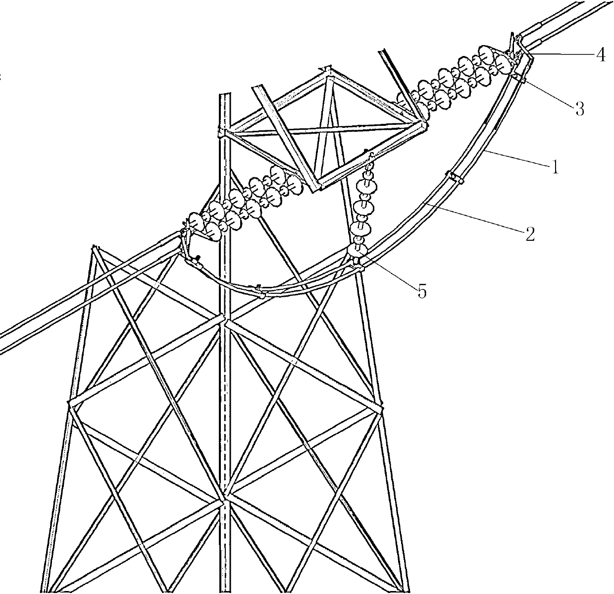
[0024] Such as figure 1 As shown, the multiconductor drainage method of the transmission line of the present invention comprises the following steps:
[0025] ① According to the design size, take two straight wires with the same synchronous length as #1 wire drainage 1 and #2 wire drainage 2, and press the two ends of #1 wire drainage 1 and #2 wire drainage 2 respectively on the upper connecting plate;
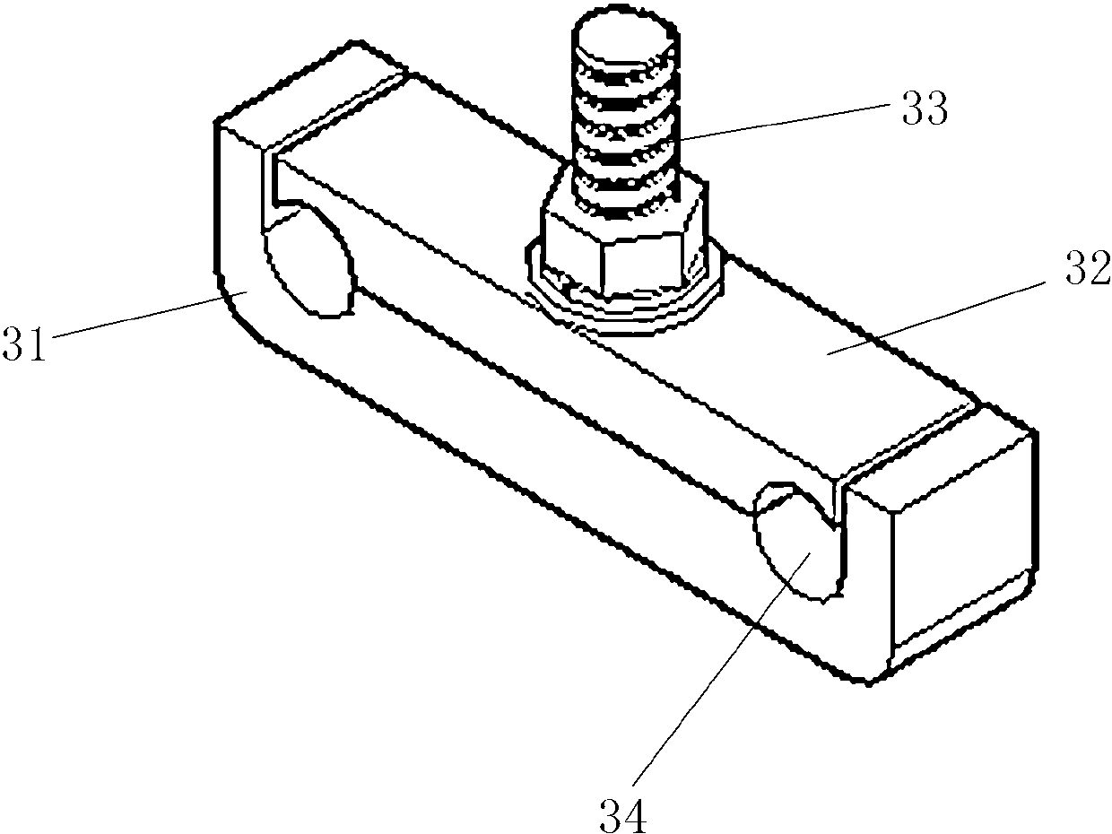
[0026] ②Place the two drains in parallel and keep both sides even. Take the center part of the two drains and install the spacer bar 3. After the installation is firm, install a spacer bar at the root of the connecting plate on both sides of the two drains, and then Install a spacer rod between the connecting plate and the center of the drainage;
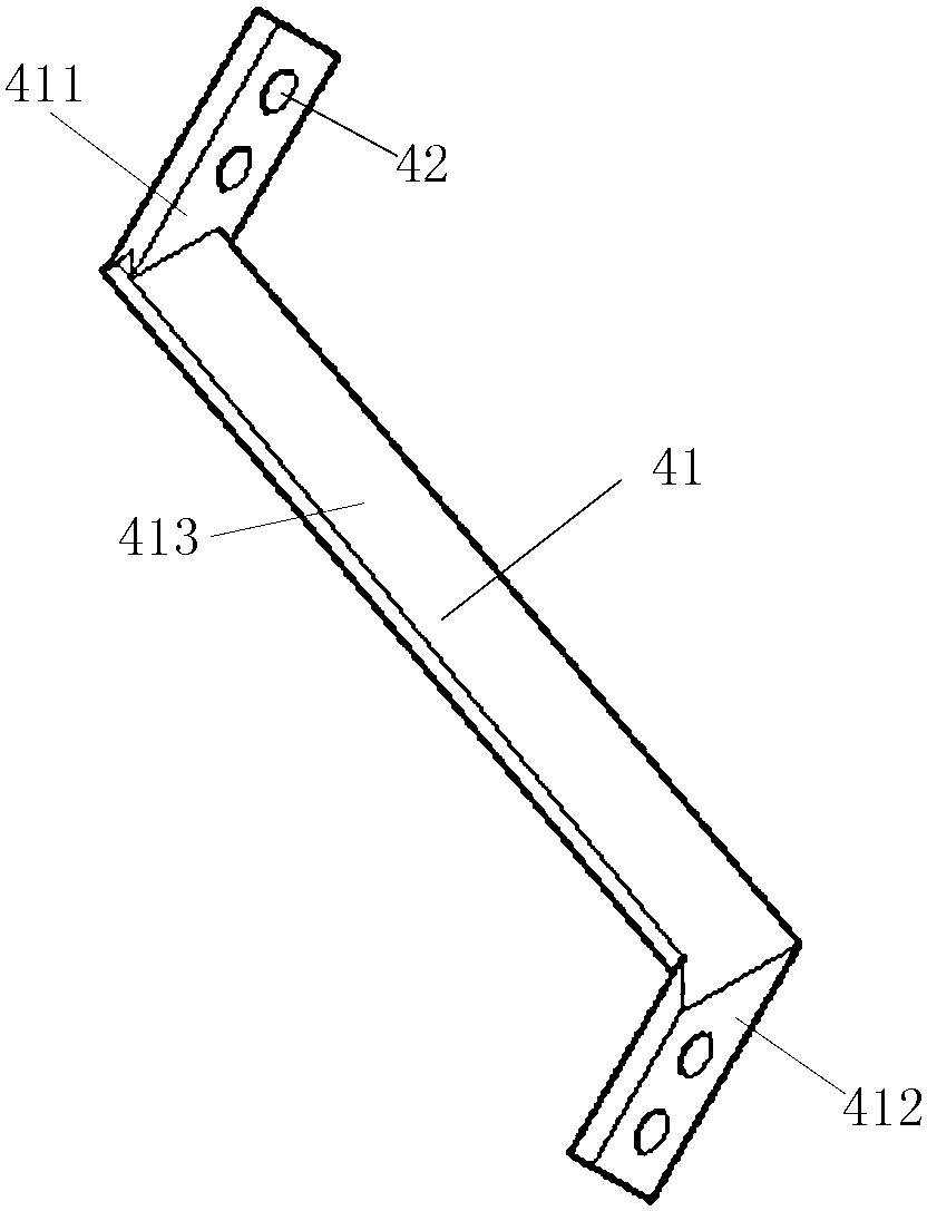
[0027] ③ Connect #1 line drainage 1 to the curved connecting plate through the connecting plate;
[0028] Such as fi...
PUM
 Abstract
Description
Claims
Application Information