
A self-locking connecting mechanism

A connecting mechanism and self-locking technology, applied in the direction of railway vehicle coupling accessories, traction devices, railway car body parts, etc. Low and other problems, to achieve the effect of simple structure, high loading and unloading efficiency, and convenient operation

Active Publication Date: 2021-09-21
CRRC SHANDONG CO LTD
View PDF9 Cites 0 Cited by
  • Summary
  • Abstract
  • Description
  • Claims
  • Application Information

AI Technical Summary

Problems solved by technology

[0003] With the development of the railway freight market, the current freight vehicles have gradually transformed into market-oriented and specialized vehicles; in some plateau areas of my country, the efficiency of road transportation is low, and it is also seriously affected by climate, geological and other conditions. Using railway transportation can alleviate the corresponding problems. However, the floor surface of existing railway transport vehicles in my country is generally high, which is not suitable for loading large cargo such as road vehicles
In response to this problem, the application of low-floor train sets was born. This train set uses a traction device to realize the connected traction between the train set and the rolling stock. The inventor found that although the floor height of the low-floor train set has been reduced, the traction device and the rolling stock There is a certain height difference between the low floors, and the connection interface between the traction device and the special low-floor vehicle needs to be opened and locked safely and quickly. Such a connection mechanism requires that the devices on both sides be symmetrical in order to ensure a reliable connection. Therefore, the current connection mechanism cannot meet the connection requirements of the traction device and the low-floor special vehicle.

Method used


Image

  • A self-locking connecting mechanism
  • A self-locking connecting mechanism
  • A self-locking connecting mechanism

Examples


Embodiment 1

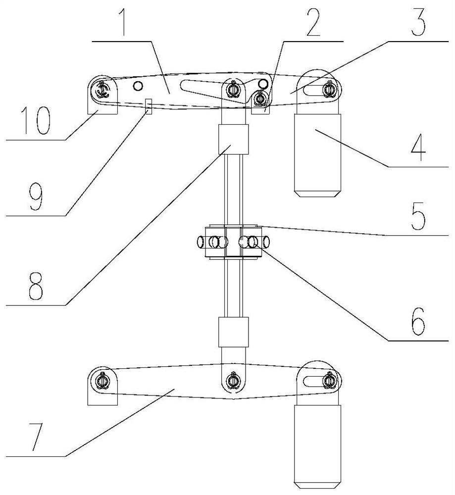
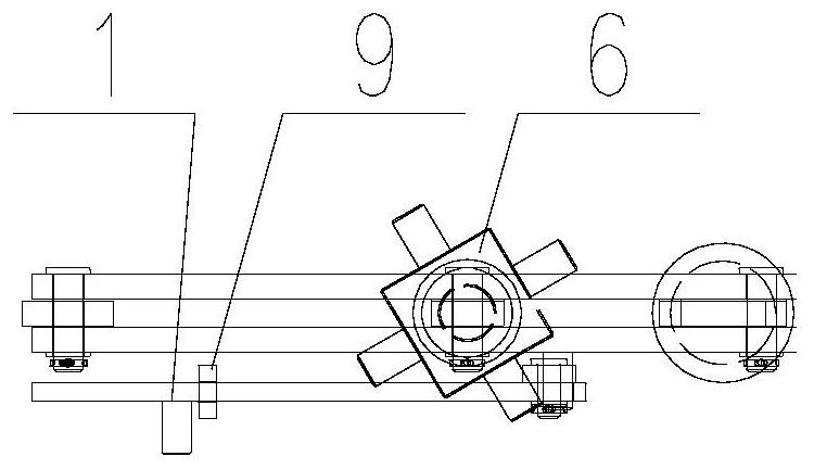
[0044] In a typical embodiment of the present invention, refer to figure 1 with figure 2 As shown, a connection mechanism that can realize self-locking includes a first element 1 and at least one second element, the second element has a first end that is movably connected with a first device such as a traction device 20, and the second element has a second The end is provided with a connecting piece that can be inserted into a second device such as a low-floor vehicle group, and the second end of the second element can be lifted, and one of the second elements has a protrusion, and the first element is arranged on the side of the second element, The first element 1 is provided with guide holes for accommodating the protrusions.

[0045] Among them, in order to realize the connection between the traction device and the low-floor vehicle group, the second element is arranged in two places up and down, and the upper and lower second elements are connected to the lifting parts. ...


PUM


Abstract

The invention discloses a connection mechanism capable of realizing self-locking, which solves the problem that the existing connection mechanism in the prior art cannot meet the connection requirements of the first device and the second device, and has the advantages of simple structure, convenient operation and high safety and reliability. Beneficial effects, the specific solution is as follows: a connection mechanism that can realize self-locking, including a first element and at least one second element, the second element has a first end that is movably connected with the first device, and the second end of the second element A connecting piece that can be inserted into the second device is provided, and the second end of the second element can be raised and lowered, at least one second element has a protrusion, the first element is arranged on the side of the second element and is movably connected with the first device, The first element is provided with a guide hole for accommodating the protrusion, and one side end of the guide hole is beyond the joint of the first element and the first device.

Description

technical field [0001] The invention relates to the field of railway wagons, in particular to a connection mechanism capable of realizing self-locking. Background technique [0002] The statements in this section merely provide background information related to the present invention and do not necessarily constitute prior art. [0003] With the development of the railway freight market, the current freight vehicles have gradually transformed into market-oriented and specialized vehicles; in some plateau areas of my country, the efficiency of road transportation is low, and it is also seriously affected by climate, geological and other conditions. Using railway transportation can alleviate the corresponding problems. However, the floor surface of existing railway transport vehicles in my country is generally high, which is not suitable for loading large goods such as road vehicles. In response to this problem, the application of low-floor train sets was born. This train set u...

Claims


Application Information

Patent Timeline
Patent Type & Authority Patents(China)
IPC IPC(8): B61G7/00B61G9/20
CPCB61G7/00B61G9/20
Inventor 吴杰李宝瑞李兴李铮马一丹张文龙
Owner CRRC SHANDONG CO LTD
Learn More