
Construction method for assembling joint beams of superimposed shear walls with openings in windows

A technology of superimposed shear walls and construction methods, applied in the direction of walls, earthquake resistance, building components, etc., can solve problems such as insufficient shear bearing capacity, inability to effectively protect wall limbs, and increased construction difficulty

Active Publication Date: 2021-09-03
WUHAN UNIV OF TECH +1
View PDF13 Cites 0 Cited by
  • Summary
  • Abstract
  • Description
  • Claims
  • Application Information

AI Technical Summary

Problems solved by technology

In actual engineering, traditional cast-in-place deep coupling beams usually have defects such as poor ductility and weak energy dissipation capacity due to too small span-to-height ratio. It cannot be produced in the deep connecting beam first, so it cannot effectively protect the wall pier
To solve the above problems, measures such as reducing the height of the coupling beam and reducing the stiffness of the coupling beam are usually taken. Although the internal force of the coupling beam can be reduced, the overall lateral stiffness of the structure will be reduced at the same time; force, but the setting of oblique reinforcement will increase the difficulty of construction; or divide the deep coupling beam into multiple coupling beams with a larger shear-span ratio to reduce the shear force at the end of the beam to solve the problem of super-reinforcement, although this can be achieved to a certain extent Improve the ductility and energy dissipation capacity of the shear wall structure under earthquake action, but its ultimate bearing capacity and lateral displacement stiffness are lower than those of the deep coupling beam shear wall

Method used


Image

  • Construction method for assembling joint beams of superimposed shear walls with openings in windows
  • Construction method for assembling joint beams of superimposed shear walls with openings in windows
  • Construction method for assembling joint beams of superimposed shear walls with openings in windows

Examples


Embodiment 1

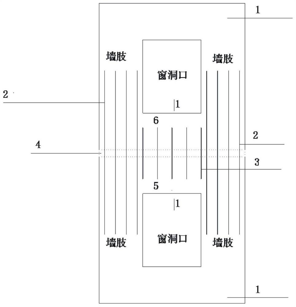
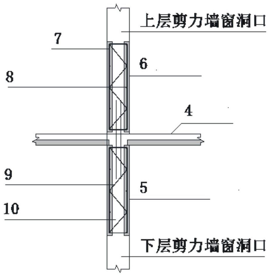
[0022] Such as figure 1 and figure 2 Shown is a double-sided laminated shear wall structure with a window opening, including prefabricated double-sided laminated shear wall panel 1 with a window opening, vertical connection reinforcement bars 2 for wall piers, vertical connection reinforcement reinforcement bars 3 for connecting beams, stacked Composite floor slab 4, post-cast core layer concrete 10. The prefabricated window-opening laminated shear wall panel 1 consists of a prefabricated inner leaf wall panel, a prefabricated outer leaf wall panel and a vertically arranged steel bar truss 9 connecting the inner and outer wall panels, and the prefabricated inner and outer leaf wall panels are arranged with Longitudinal and horizontal distribution of steel bars, among them, the layout of vertical and horizontal force-bearing steel bars in the laminated shear wall panel 1 with window openings must meet the requirements of the code. The prefabricated window opening laminated s...

Embodiment 2

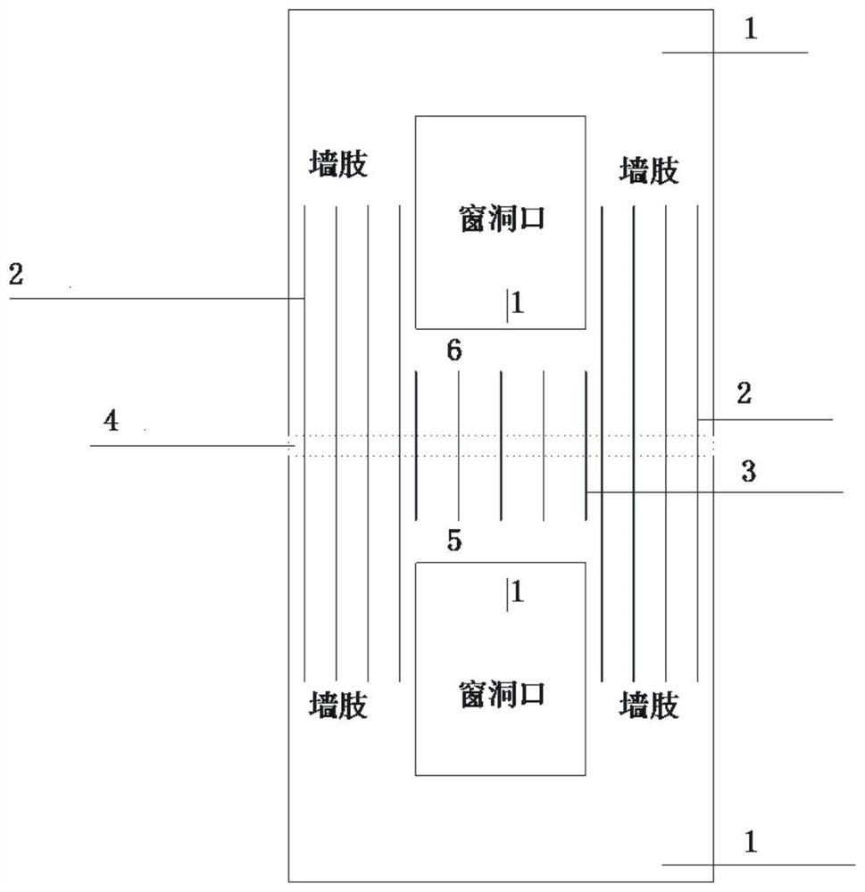
[0029] Embodiment 2 is a single-sided laminated shear wall structure with window openings. Such as Figure 3 to Figure 4 The upper and lower laminated deep connecting beam single-sided laminated shear wall structure includes precast concrete window hole laminated shear wall panel 1, vertical connecting steel bars 2 of wall piers, vertical connecting steel bars 3 of connecting beams, Laminate floor slab 4, post-cast core layer concrete 10. The above prefabricated concrete laminated shear wall panels are provided with window upper wall connecting beams 5 and window lower wall connecting beams 6, and the connecting beams are provided with stirrup bars 7, longitudinal stress bars 8, truss steel bars 9, and FRP insulation connectors 11. Insulation board 12 and outer leaf board 13. Laminated shear wall panels 1 with window openings include prefabricated laminated wall panels for the inner and outer leaves, steel bar trusses 9, FRP insulation connectors 11 and insulation panels 12 ...


PUM


Abstract

The invention relates to a construction method for assembling a composite shear wall coupling beam with a window hole, which comprises: prefabricating a composite shear wall panel including a window upper wall coupling beam and a window lower wall coupling beam, transporting to the construction site for assembly; The vertically connected steel bars between and the post-cast core layer concrete will effectively connect the upper and lower laminated wall panels. In the present invention, by changing the number of vertically connected steel bars in the post-cast concrete of the upper wall of the window and the core layer of the wall below the window when assembling the laminated wall panels with the window hole, the "full-through joint, zero joint" and "half-through joint" can be formed respectively. Different forms of coupling beams such as "semi-through joints and equal connections" and "semi-through joints and equal connections" can meet different seismic requirements. Among them, the "semi-through joints and weak connections" upper and lower laminated deep coupling beams can realize a multi-stage working mechanism; This kind of connecting beam can not only make the structure have sufficient lateral stiffness and deformation resistance under the action of frequent earthquakes and fortification intensity earthquakes, but also can be transformed into a "double connecting beam" force mechanism under the action of rare earthquakes to meet the requirements of the structure. Performance goals for different stages.

Description

technical field [0001] The invention relates to the technical field of building engineering construction, in particular to a construction method for assembling a window-opening superimposed shear wall coupling beam that can realize a multi-stage working mechanism. Background technique [0002] As an important part of the shear wall structure system, coupling beams are important components to improve the mechanical performance of shear walls and core tubes in high-rise buildings, and have a decisive impact on the seismic performance of connected shear walls. In actual engineering, traditional cast-in-place deep coupling beams usually have defects such as poor ductility and weak energy dissipation capacity due to too small span-to-height ratio. It cannot be produced in the deep connecting beam first, so it cannot effectively protect the wall pier. To solve the above problems, measures such as reducing the height of the coupling beam and reducing the stiffness of the coupling ...

Claims


Application Information

Patent Timeline
Patent Type & Authority Patents(China)
IPC IPC(8): E04G21/00E04B2/00E04B1/98E04H9/02E04C2/06E04C2/30E04B1/61
CPCE04B1/61E04B1/98E04B2/00E04C2/06E04C2/30E04G21/00E04H9/02
Inventor 谷倩邓庆曹任辉谭园田水
Owner WUHAN UNIV OF TECH
Learn More